chisel plough diagram 3d models
7684 3d models found related to chisel plough diagram.
prusaprinters
You can view the new document in the uploaded files: Final_x_axis_Assembly_Diagram_Exploded_view_v1_11_17_2016.pdf (It is definitely worth taking a look at the picture assembly document as well still) Edit 5: I have a limited number of the metal...
prusaprinters
Change the font to Impact and adjust positioning and size to your desire.Indent the two letters to 0.1cm using the extruded cut tool.Design Choices:We first started off by looking at the model and drawing a diagram with 2x the dimensions so each...
thingiverse
This is how I wired up the mini XLR 4 pin connectors: 1 - Left + 2 - Left - 3 - Right + 4 - Right - The standard 3.5mm jack wiring arrangement is: Tip - left + Ring (middle) - Right + Sleeve (base) - GND (left & right -) (need to add a wiring...
thingiverse
Make sure you check everything with the corresponding official wiring diagram (not here!) - Small screwdriver Shorten cables and/or make connections as seen fit. Make sure all cables are under no strain. No cables should be touching the MOSFET...
prusaprinters
A perfect Christmas gift for Raspberry Pi and Renewable Energy lowers. This complex design is an interactive Renewable Energy demonstration Raspberry Pi (RPI) case with a process diagram about the wind solar hybrid electricity generation. It contains...
prusaprinters
A little light soldering was also required. Custom Section Electronics and parts By request I've added a wiring diagram. Parts are roughly to scale. There is also a full parts list. Where possible I shopped at <a...
thingiverse
Assembly ------ Please use this diagram as a reference: 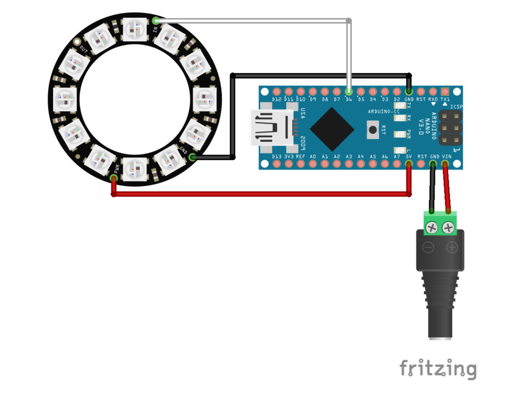 **Note**: It should not be necessary to use...
prusaprinters
... are ok with you selling the shields for production cost. However, we do not want to see these shields on eBay for $50. Print instructionsSupports are not necessary. Print with at least 3 perimeters, about 30% infill. Ideally, print it from PETG.
prusaprinters
The only part that requires a little bit of support is the Top piece for where the switch goes.Wiring Up Electronics:Below you an see a picture with the wiring diagram of how to connect all the wires needed for the project. Make sure your Arduino is...
prusaprinters
English: Hello I have created several bases for different 1 metre aluminium LED profiles. The LED strips used here are WS2812B (NeoPixel) 144LEDs/m. The used controller is a socketed ESP8266-12F. The PCB format is 60x40mm. The aluminium profiles are...
prusaprinters
The eyes should be completed and glued to the head before attaching the beak.5 - Refer to the assembly diagrams in the pictures section as well as the uploaded pictures for putting the model together. ...The model is meant to be glued.</p><p>Do...
prusaprinters
Make sure they are in the right orientation!Follow the wiring diagram (at the end of the photo gallery) to solder the resistors and wires across the keyswitches.Solder the wires to the Arduino Micro.If doing the “Both” or “Combinable” version, cut up...
thingiverse
... 6 - Refer to the assembly diagrams in the pictures section as well as the uploaded pictures for putting the model together. The model is meant to be glued. Do not hesitate to ask questions, feedback is essential to making better models. ...
thingiverse
You can follow the diagram for wiring, using your best judgment for wire lengths. There is only one solder point recommended while using the jumpers; if you do not want to use the jumpers, you can wire it however is best for your setup. The function...
prusaprinters
Lesson Plan: With a partner, recreate a ghost clip using Solidworks. The goal is to be both accurate and coordinated with my partner to create a replica ghost clip with our initials engraved on it.Construction Instructions:Constraint...
prusaprinters
Base is soldered according to the wiring diagram at the WLED quick start guide7.3. ...(Optional) Sensor can be attached to switch the Leafs on/off and change color</li><li>Once the pattern is finished, the covers need to be prepared by breaking away the...
thingiverse
This new setup was originally developed for older FlashForge printers due specifically to compatibility with certain features that weren't possible until newer upgrades got released.\nThe rod itself measures longer by 8.5 mm from the standard...
myminifactory
... 6 - Refer to the assembly diagrams in the pictures section as well as the uploaded pictures for putting the model together. The model is meant to be glued. Do not hesitate to ask questions, feedback is essential to making better models. ...
myminifactory
... 6 - Refer to the assembly diagrams in the pictures section as well as the uploaded pictures for putting the model together. The model is meant to be glued. Do not hesitate to ask questions, feedback is essential to making better models. ...
thingiverse
The circuit diagram is in the list of photos (update March 2nd 2023: I found it again, yay!): this is as seen from the TOP. I made some small changes in the project source code and committed these to this forked repository:...
prusaprinters
Make sure they are in the right orientation!Follow the wiring diagram (at the end of the photo gallery) to solder the resistors and wires across the keyswitches.Solder the wires to the Arduino Micro.If doing the “Combinable” version, cut up cables...
myminifactory
... 5 - Refer to the assembly diagrams in the pictures section as well as the uploaded pictures for putting the model together. The model is meant to be glued. Do not hesitate to ask questions, feedback is essential to making better models. ...
myminifactory
They prefer to see a model of a bacterium rather than just seeing it in a 2D diagram. The models I created are divided into two parts, so you can look inside the model. Inside the model, I pasted a picture of the interior of a microorganism. Here...
myminifactory
Top left is a close-up of the animal cell membrane, and bottom right is a diagram of the plant cell structure. Project Overview: The project involves creating a chemical kit that includes sixteen objects and permits learning chemistry and biology...
prusaprinters
There's a diagram above for reference. All you need to do is connect one positive (+) lead from each LED strip together and one negative (-) lead from each LED strip together so you have a single (-) wire and a single (+) wire. I found the easiest...
prusaprinters
A compatible remixed fan mount and duct can be found below.Note: 40mm version shown in action.ProsDirect drive conversion+10mm in X axis build volume (260mm total)BLtouch mountAccelerometer mountCompact and cleanGood cable managementVery...
prusaprinters
Wiring diagram and keyboard layout will come along later.Name is lame, might change it later. That's all for now.</p><p>Reddit reference thread: <a...
thingiverse
►COMPONENTS FOR THIS PROJECT Digital DC 100V 10A Voltage Current Meter DC 5-24V: Aliexpress DC-022 5.5x2.1mm DC Power Socket: Aliexpress | Shopee Thailand KCD11 Rocker Switch: Aliexpress | Shopee Thailand 6mm SPDT Slide Switch (2 Positions 3...
thingiverse
- Connect the stepper motor wires according to the diagram above. - Install the new mount and fan shroud onto the printer. - Calibrate your extruder to ensure proper alignment. Note: This stepper motor wiring differs from the wiring of the stepper...
myminifactory
... lowest. 5 - Refer to the assembly diagrams in the pictures section as well as the uploaded pictures for putting the model together. The model is meant to be glued. ...Do not hesitate to ask questions, feedback is essential to making better models.