132:1 Hypcycloid gearbox for NEMA17 stepper motors
prusaprinters
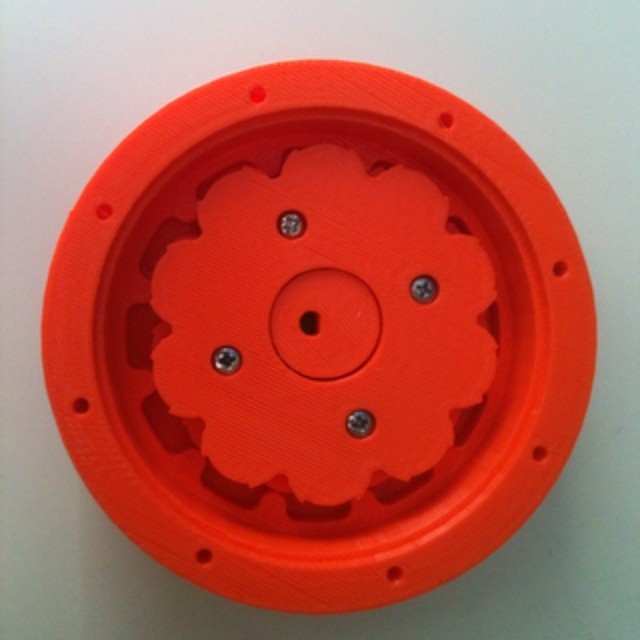
<p>I'm building robot arms that I plan to make available to everyone through <a href="https://www.marginallyclever.com/">my website</a>. To get enough power to move the arm the way I want, I needed a gearbox, which is a way to trade speed for power. Nobody I can find makes to my spec, so I created my own. I'd love your help to improve this design, so I've released the plans for my first version here. <a href="http://instagram.com/p/piMRPxofLx/">See it in action</a>, then <a href="http://hackaday.io/project/945-6DOF-Robot-Arm">read more about the arm</a>, then <a href="https://www.marinallyclever.com/">buy a robot and support my work</a>.</p> <p>Special thanks to <a href="/LoialOtter">http://www.thingiverse.com/LoialOtter</a> for making my first hypocycloid gearbox about 3 years ago. It's taken this long to actually put it to use!</p> <p>Special thanks to <a href="/johnbiehler">http://www.thingiverse.com/johnbiehler</a> for printing this copy. My machine wasn't up to the task and he really came through for me.</p> <p>Edit: So the post mortem about hypocycloids... the big problem is that the forces inside are uneven. A planetary gear has three planets to balance the forces on the sun, keeping the sun in place. a hypocycloid - one or two stage - does not. the center shaft bends (even a little bit) and the interior gear jams. Long story short, these gears don't work in the real word unless you really really know what you're doing (like how to avoid the bending because you know your material strength properties and your torque forces and more I don't know)</p> <p>Support me through Patreon: <a href="https://www.patreon.com/imakerobots">https://www.patreon.com/imakerobots</a></p> <p>Or make a one time donation: <a href="https://www.paypal.me/imakerobots">https://www.paypal.me/imakerobots</a></p> <p>Every like, share, and subscribe helps!</p> <p>Blog: <a href="http://marginallyclever.com/">http://marginallyclever.com/</a></p> <p>Instagram: <a href="https://www.instagram.com/imakerobots">https://www.instagram.com/imakerobots</a></p> <p>Facebook: <a href="https://www.facebook.com/MarginallyClever">https://www.facebook.com/MarginallyClever</a></p> <p>Twitter: <a href="https://twitter.com/aggrav8d">https://twitter.com/aggrav8d</a></p> <p>Discord: <a href="https://discord.gg/Q5TZFmB">https://discord.gg/Q5TZFmB</a></p> <h3>Instructions</h3> <p>Design</p> <hr/> <ul> <li>I used <a href="https://www.marginallyclever.com/other/hypocycloid-generator.html">https://www.marginallyclever.com/other/hypocycloid-generator.html</a> to generate the gear profiles as DXF files.</li> <li>I used solidworks to model the parts, check for interferences, and add tolerances.</li> <li><a href="https://www.thingiverse.com/thing:321679">Previous work with bearings</a> helped make sure parts would move smoothly.</li> </ul> <p>Assenbly</p> <hr/> <ul> <li>I fixed the stepper motor to the outer casing with M3x10 screws.</li> <li>The 11lobe has one smooth side and one shelled side. I put the 11lobe into the outer casing smooth side up. 11 lobe and outer casing will create a 12:1 reduction.</li> <li>I put the pinion on the motor shaft and slid it down until the groove along the center matched the groove on 11lobe, then secured the pinion to the motor with an M3 set screw. The motor shaft has a flat side.<em>If the pinion hole is a little too small, try a 7/32 (5mm) drill bit to clean it out. This part is very hard to print in ABS!</em></li> <li>I very carefully used tweezers to put 1/8" metal bearing balls into the groove and added some silicone lubricant. Don't stress! Just go slow and do them one at a time, you'll get there.</li> <li>I started three M3x10 screws in the shelled side of the xlobe. I screwed until they were just at the smooth side. Then I put the xlobe smooth side down onto the pinion. I used the one open M3 hole to line up with the 11lobe, then screwed both halves together.</li> </ul> <p><em>In a perfect world both lobes are flush to each other. In real life if your prints aren't perfect then your lobes will pinch the bearings so hard that they can't turn. Firm enough to keep the balls in place, loose enough to still move is really iffy, but that's why this is a prototype.</em></p> <ul> <li>I slid the final stage over xlobe. xlobe and final stage and will create 11:1 reduction. 12*11=132.</li> <li>Again I carefully placed 1/8" bearing balls in the outer raceway between final stage and outer casing.</li> <li>I used M3x45 screws to attach the retaining ring. The ring keeps the balls from popping out. The screws add strength to the outer casing. The balls improve movement of the final stage and prevent it from drifting out of alignment.</li> <li>I attached the stepper motor to a 3D printer control board and programmed it to step very slowly in one direction.</li> <li>Lastly, I made a mark with a sharpie so I could see how far the final stage had turned.</li> </ul> Category: Robotics
With this file you will be able to print 132:1 Hypcycloid gearbox for NEMA17 stepper motors with your 3D printer. Click on the button and save the file on your computer to work, edit or customize your design. You can also find more 3D designs for printers on 132:1 Hypcycloid gearbox for NEMA17 stepper motors.