16 Valve DOHC Cylinder Head for Inline 4 Engine
prusaprinters
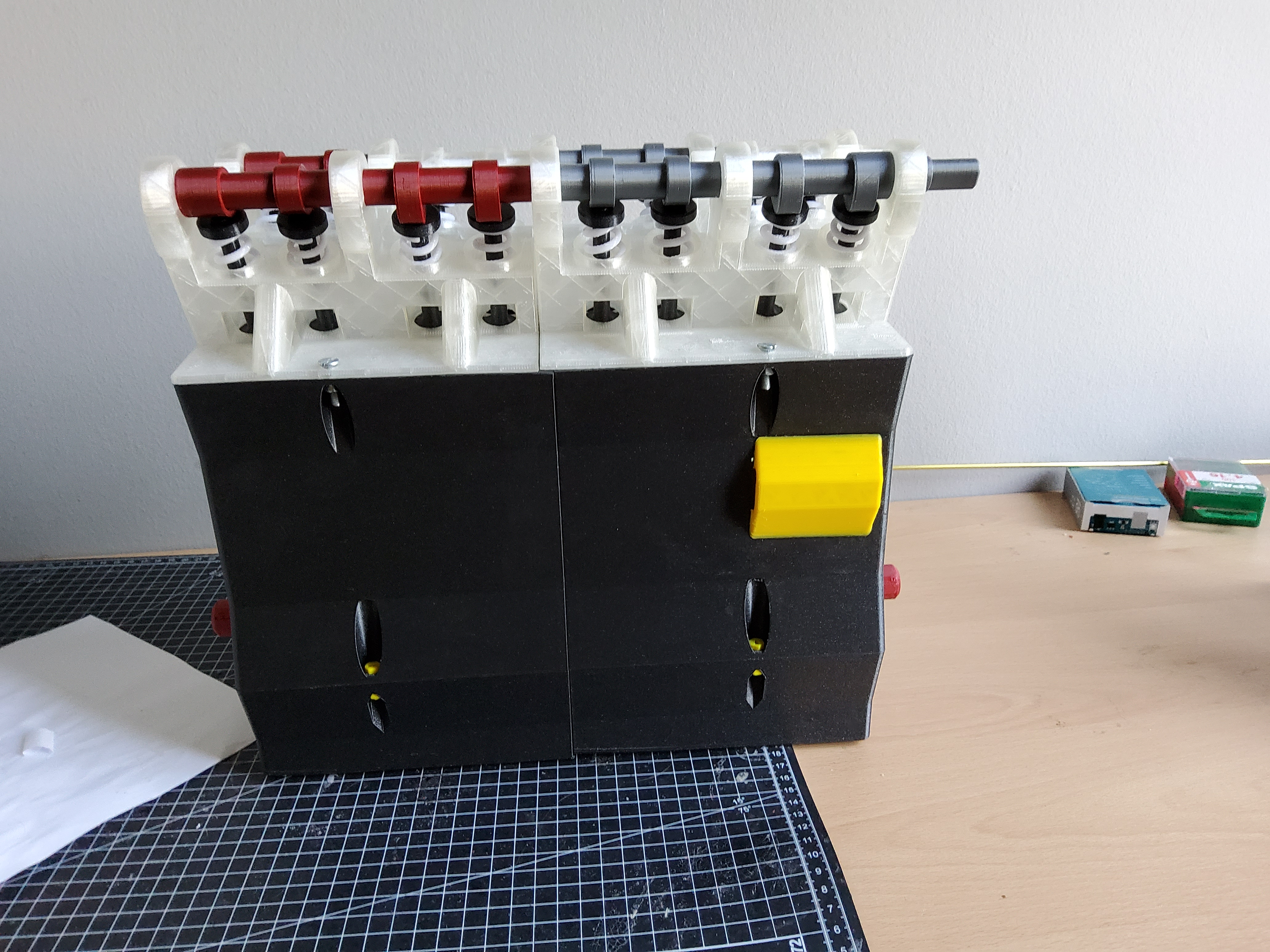
<p>Here is my attempt at modelling a 16 valve cylinder head with two overhead cams. This model fits on top of my inline 4 engine, which can be found here: <a href="https://www.printables.com/model/120676-model-inline-4-cylinder-engine">https://www.printables.com/model/120676-model-inline-4-cylinder-engine</a> . This kind of arrangement is extremely common in small economic cars (Honda, Ford, Opel/Vauxhall, VW etc.) and fast motorcycles, for example the Yamaha R6 or the Moto GP Bikes from Suzuki have inline 4 engines with 16 valves actuated by two overhead cams. In a motorcycle this arrangement allows for a high revving engine that produces a lot of power high up in the rev range, which means you go fast.</p><p> </p><p>Additional hardware required: 4 m5 screws and nuts</p><p> </p><p>Top tip:</p><p>before printing out various pieces multiple times and finding out that they might not fit together the way they are supposed to, print out Valve stem.stl, Valve top.stl and “camshaft bearing top.stl” once and try fitting them where they are supposed to go, if they fit, then you can continue to assemble as normal, if not, you might have to do some sanding or scaling to the pieces to make them fit.</p><p> </p><p>I also recommend that the valve return springs are printed out of PETG instead of PLA, because that will make the support removal process a lot easier.</p><p> </p><p>Assembly instructions:</p><ol><li>print out every piece, it should say how often you have to print each piece, if it doesnt, print it once and that will be enough.</li><li>After printing all the pieces, check to see if they fit correctly by placing “Baseplate small.stl” on a table, and from below inserting one “Valve stem (print 16 times).stl” from below into one of the small holes for the valves. Then take one “Valve return spring (print 16 times).stl” and place it into the circular seat. The return spring is slightly conical, the wider diameter part of the spring is the bottom part and fits better into the circular space. Afterwards, take one “Valve top (print 16 times).stl” and screw it onto the valve stem so that the return spring is compresses a little bit, the top of the valve stem and cap should be level so that there is a flat surface for the cam to move along. Next, take one of the “camshaft rear (print twice).stl” pieces and place them in the top portion of the cylinder head, the semicircular lower bearing half of the camshaft. The camshaft should be able to rotate freely. Next, take one of the “camshaft bearing top (print 10 times)” and slide it into its correct slot above the camshaft, there should be a little play but the small baseplate with the lower camshaft bearing and the upper camshaft bearing should slide together without much force required. You can check to see if all the parts fit correctly and compare with one of the uploaded pictures.</li><li>most difficult step completed (step 2), to completely assemble your cylinder head, you basically have to repeat what you did in step two 16 times. After taking out the rear camshaft, insert a valve stem from below into the small baseplate and then from above first the valve return spring and finish off with the valve top. Again compress the return spring a little bit but the top surface of the valve stem and valve top should be flush with one another. This step is completed when you have 16 valves in your cylinder head, but no camshaft is yet fully attached.</li><li>The two camshafts themselves are made out of two pieces, “camshaft rear (print 2 times).stl” and “camshaft front (print 2 times).stl”. The rear camshaft fits into the front camshaft but NOT the other way around. It is important that the two camshaft halves are fitted together correctly: the 2 cams closest to each other have to be at 90 ° to each other, pictures are provided to hopfully better explain how the camshafts are supposed to fit together, this has to be done with all camshaft pieces. The front camshaft also has a polygon hub in order to fit a timing gear, however I am still waiting on parts before I upload the timing assembly for the whole thing.</li><li>Fit the two fully assembled camshafts onto the top of the cylinder head and then slide the 10 top camshaft bearings into each slot to fully secure both camshafts. The camshafts should not be able to move side to side, but should be able to rotate freely and now can actuate all 16 valves.</li></ol><p>Your 16V DOHC cylinder head is now fully assembled, if you have my model of an inline 4 engine, you can attach it to the top of that model with 4 m5 screws and nuts in order to make a more complete model. As mentioned above, the timing assembly will hopefully soon follow.</p><p> </p><p>P.S. the big black box at underneath the cylinderhead in the pictures is the engine model, which is not necessary to assemble this model</p>
With this file you will be able to print 16 Valve DOHC Cylinder Head for Inline 4 Engine with your 3D printer. Click on the button and save the file on your computer to work, edit or customize your design. You can also find more 3D designs for printers on 16 Valve DOHC Cylinder Head for Inline 4 Engine.