1U Rackmount Cluster - Raspberry Pi 3B+ / 4B
prusaprinters
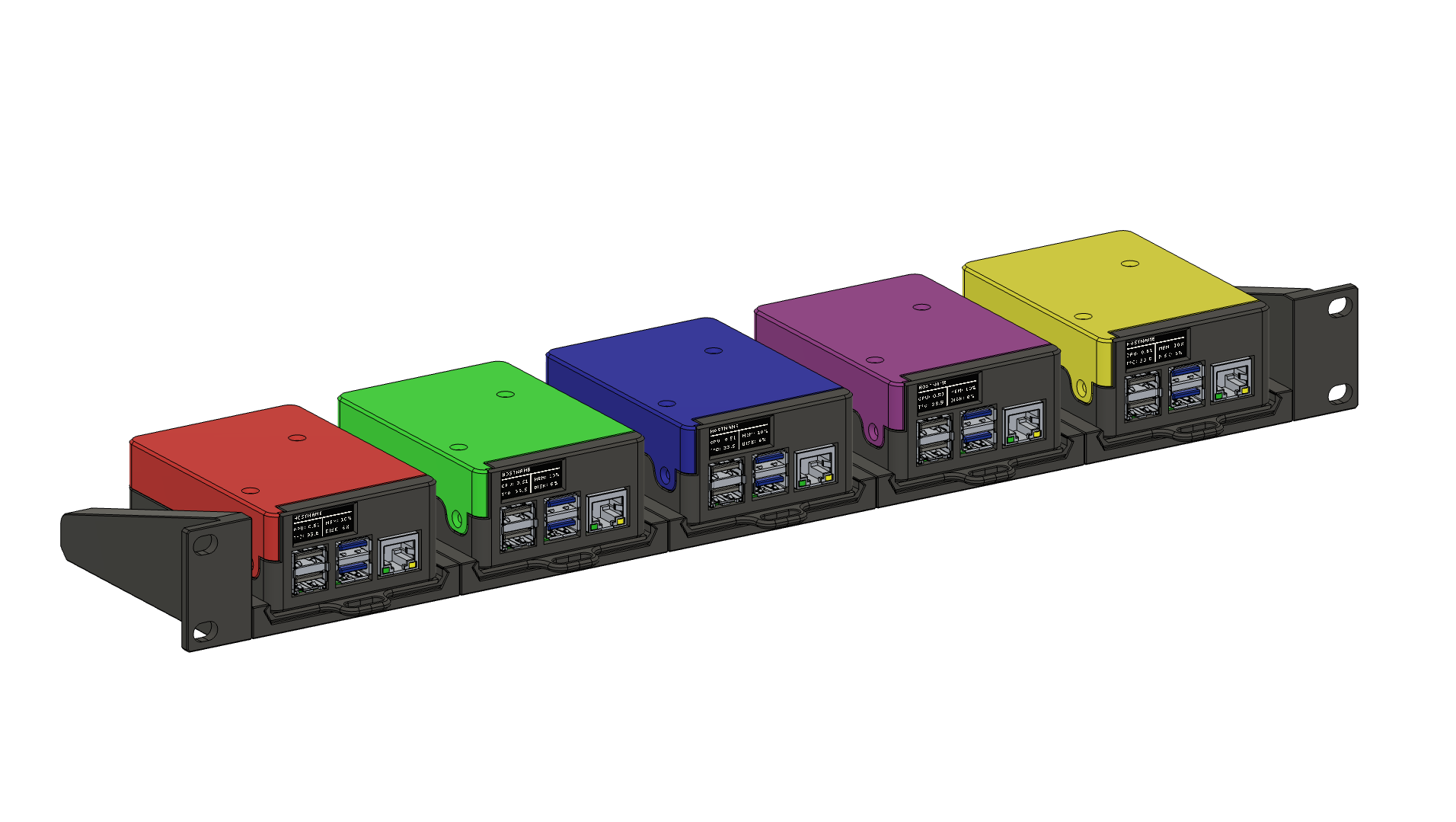
<p>Hey everyone!</p><p> </p><p>I present my version of the 1U Rackmount Cluster, inspired by russross' design (<a href="https://www.thingiverse.com/thing:4125055">HERE</a>), and revnull's OLED addition (<a href="https://www.printables.com/model/150104-raspberry-pi-4-oled-mount">HERE</a>). My version here is a full-scratch design built from the ground up to be completely modular, and is able to be used as a standalone RPi 3 or RPi 4 case powered by PoE. This project is an evolving project as well, and will include additional designs as I have the time to make and publish them (e.g. 1 or more drawers for storage, etc.).</p><p> </p><p>First and foremost, AS OF NOW, THIS IS A PoE-POWERED DESIGN ONLY. If you're not interested in PoE, but still want to build this rack, I will likely add support for USB power after some initial feedback. </p><p> </p><p>Also to note, this design, while tested pretty heavily by me, has not been tested by your printer or print settings. What that means, is this should be considered “beta” until more people have tested it. If you aren't interested in testing and giving feedback, please wait until enough people have tested it to be comfortable for a “full” release. With that, I will be waiting to add the CAD files for this until it has been tested, just so there aren't versions of remixes with issues in them.</p><p> </p><p>Final note, this is NOT a cheap project, but it is still significantly cheaper than many of the commercial offerings. I did not go out of my way to make sure the build was cheap, I went out of my way to make sure it was easy to assemble and had a bunch of cool things that people would want to use. If you're able to afford a bunch of Pi's for this project, I assume you don't mind spending the bit extra on the parts.</p><p> </p><p><strong>Disclaimers out of the way, let's get to the good bits…</strong></p><p> </p><p>This design <strong>REQUIRES</strong> specific parts to go together properly, all of which are listed below. Feel free to stray from the list at your own risk! I am not responsible for the parts not going together if you stray from the bill of materials listed.</p><p> </p><p><strong>Print Requirements:</strong></p><ol><li><strong>No supports!</strong></li><li>Parts are already oriented properly for printing, do not flip them (rotation is fine).</li><li>Designed with 0.4mm nozzles in mind, but Arachne should help with larger nozzles. If you have issues please use a 0.4mm nozzle.</li><li>I recommend 3-4 perimeters, with 4-5 top and bottom layers, and a 0.2mm layer height (0.4mm wide x 0.2mm height).</li></ol><ul><li>You will need 5 total Rack Modules and Rack Sleds, and 1 of each Rack Left Ear and Rack Right Ear to make a single 19" 1U rack module.</li><li>There are holes printed on top of a single layer of bridging on the left edge of each Rack Module. You will need to push a heatset insert through the bridging to get it into position (see images).</li><li>Each lower-half of the Pi Case (RPi 3B+ and 4B) requires 3 heatset inserts to attach the top. Use care when inserting these heatsets; there is no backer to prevent pushing the inserts too far in.</li><li>The top half is the same between both RPi bottom models. Do NOT over-tighten the screws holding the top in place or you will crack the tabs and have to reprint the model.</li><li>Any questions or issues, please let me know.</li></ul><p> </p><p><strong>Part Requirements (all Amazon US non-affiliate links, if out of the US, you are on your own to find the parts needed in your country):</strong></p><p> Big Parts! - </p><ol><li><strong>PoE Hat (UCTRONICS)</strong> - <a href="https://www.amazon.com/dp/B082ZLDMZ6">HERE</a> - This PoE hat is required due to size constraints, as well as easy break-out for the i2c connectors for the OLED display.</li><li><strong>OLED Display (Frienda)</strong> - <a href="https://www.amazon.com/dp/B08L7QW7SR">HERE</a> - There are many types of these OLED displays. As far as I'm aware, any of them shaped like this should work, but this is the one I've personally tested. They all appear to be clones of the Adafruit model that revnull used in his design. Please note, this specific model does NOT have the pin header soldered info place and will require soldering.</li><li><strong>5015 Blower Fan (WINSINN)</strong> - <a href="https://www.amazon.com/dp/B07DB6132Q">HERE</a> - Once again any type of 5015 should work here, but I've personally tested the WINSINN model listed. If you aren't doing 4-5 Pi's, buy in smaller quantities. 12v works well under-volted to 5v and still provides a significant amount of airflow, however 5v fans are available if you're going to have these in a noisy server rack anyway. See number 8 below for options if you have existing 5015 blowers.</li><li><strong>Raspberry Pi 3B+ / 4B</strong> - I'd suggest finding these on your own. Good luck.</li></ol><p> </p><p> Small Parts! -</p><ol><li><strong>M3 4mm (depth) x 5 mm (width) Heatset Inserts</strong> - <a href="https://www.amazon.com/dp/B09MCW7ZN5">HERE</a> - This design uses a LOT of heatset inserts to make assembly and disassembly significantly easier and more repeatable without stripping plastic. These are <strong>REQUIRED</strong>, and required to be the correct size and depth (6mm deep heatsets will <strong>NOT</strong> work in most locations).</li><li><strong>M3x6 FHCS Machine Screws</strong> - <a href="https://www.amazon.com/dp/B01E5EOIWW">HERE</a> - The full 1U Rack design with 5 Pi's will use nearly 50 of these screws. If the count isn't just about perfect, you may be a screw short (fair warning, order more than 50 if needed).</li><li><strong>M2.5x5 or 6mm Screws</strong> - Only 4 needed per Pi Case to secure the Pi. If you don't have the required fasteners, I'd recommend a kit of multiple M2.5 screw lengths to have for future use. You will need a total of 20 screws for a full rack of Pis. <a href="https://www.amazon.com/dp/B09FPL5QV8">THIS</a> kit is cheap and has M2, M2.5, and M3 screws.</li><li><strong>10mm x 3mm Foam Tape</strong> - <a href="https://www.amazon.com/gp/product/B07L6K4SNC">HERE</a> - Used to both cushion and seal the display to the front of the Pi Case. I would not suggest going thicker than 3mm. This link is for 4 METERS of foam tape. If you don't have additional uses for the foam tape, try to find a smaller quantity, or save the rest for later.</li><li><strong>#10 / M5 all-thread rod</strong> - Check your local hardware store. You will need a rod 17.625" (17 and 5/8") or ~445mm long. 1/4-20 all-thread will NOT work (it's too large), same with M6 all-thread. <strong>ALTERNATIVE</strong> - You can also use a 5mm rod in place of the all-thread rod. I personally used a 5mm carbon fiber rod that I had on-hand.</li><li><strong>Female to Female Dupont Connectors</strong> - <a href="https://www.amazon.com/dp/B09FPL5QV8">HERE</a> - Required to connect display to i2c bus. Please note, you will need to flip the connection from one end to the other on the i2c pins so that SCL and SDA connect to the match on each board.</li><li><strong>(Optional) - Raspberry Pi Heatsink</strong> - <a href="https://www.amazon.com/dp/B079FP1FWR">HERE</a> - Size constraints require a heasink shorter than 10mm. This one skirts through at 7mm tall, and has been tested working. Use other heatsinks at your own risk. The heatsink only gains a few degrees celsius over airflow alone.</li><li><strong>(Optional) - Boost Converter</strong> - <a href="https://www.amazon.com/dp/B089JYBF25">HERE</a> - If you want to use 12v or 24v fans at speeds higher than what 5v can offer, these boost converters will likely be cheaper than buying a new set of 5015 fans if you have some on-hand. I suggest using some double-sided tape like 3M VHB tape to stick the board to a side wall for mounting (sold separately of course).</li></ol><p> </p><p><strong>Assembly:</strong></p><p> Pi Case -</p><ol><li>Insert 5x heatsets in the lower-half of the Pi Case (both 3B+ and 4B models), including 2x in the sides of the case, 1x in the rear of the case, and 2x on the bottom of the case if using the case in a rack <strong>(standalone Pi cases can leave these 2 out)</strong>.</li><li><strong>Remove any inserted SD card from your Pi (you have been warned)</strong> and slide the Pi into place in the lower-half of the case. It may take some wiggling to get the Pi into place. Attach the Pi with 4x M2.5x5 or M2.5x6 screws.</li><li>Install the PoE hat's included heatsink onto the PoE chip, then install the PoE hat onto the RPi 3B+ / 4B.</li><li>Solder the pin header onto the OLED display keeping the pin header FLUSH to the front of the PCB (does not protrude through the front of the holes). If you have an OLED display with a pre-soldered pin header, trim the pin header flush to the board on the front. <strong>Install 3mm Foam Tape to the back of the OLED display</strong>, and slide the OLED display into the slot in the lower half of the Pi case.</li><li>Using the Female to Female Dupont connectors, connect the OLED display's <strong>GND, VCC, SCL and SDA</strong> connections to the <strong>GND, 3V3, SDA and SCL</strong> connections on the PoE hat. <strong>Please note that the orientation of the SDA and SCL pins are flipped from one board to the other (make sure SCL goes to SCL and SDA goes to SDA).</strong></li><li>Grab a 5015 blower fan and insert 2x heatsets into the holes on the <strong>BOTTOM</strong> of the fan. Set the fan into place and secure it to the top half of the Pi Case with 2x M3x6 FHCS machine screws into the heatsets just installed. Plug the fan connector into the PoE Hat's 5v output. Please note, you may have to slightly bend the pins to get a good connection with the display Dupont cables installed. Alternatively, re-crimp the 5015 fan wires to Dupont headers and slide the connector into place.</li><li>While making sure to keep wires out of the way of the fan, slide the top-half of the Pi Case onto the bottom-half of the Pi Case. Secure the two halves together with 3x M3x6 FHCS machine screws. <strong>DO NOT OVERTIGHTEN THESE</strong> or you will crack the mounting tabs and have to reprint the top half again.</li></ol><p> </p><p> Rack Modules -</p><ol><li>Grab a Rack Module and insert 2x heatset inserts through the bridge on the left side and into the hole under the bridge. Be sure to keep pressure on the heaset pushing it AWAY from the outer wall of the print (towards the middle of the module). <strong>Repeat this setup for the remaining 4 modules, as well as the Rack Right Ear.</strong></li><li>Assemble all 5 rack modules together using 2x M3x6 FHCS machine screws per module, and install Rack Right Ear using the same 2x M3x6 FHCS machine screws.</li><li>Install all-thread rod into hole at left rear of assembled module, <strong>leaving no more than 7mm of rod sticking out of the end</strong>. If you have more than 7mm of rod sticking out after fully inserting the rod, double-check that the rod is fully seated by removing the Rack Right Ear and checking for insertion length. If needed, trim all-thread to fit requirement of no more than 7mm of rod stick-out.</li><li>Slide Rack Left Ear over exposed all-thread rod and rotate into place under the Rack Module. Secure the Rack Left Ear to the first Rack Module with 2x M3x6 FHCS machine screws. The module itself is complete.</li><li>For each Pi, grab a Rack Sled and install the Rack Sled to the lower-half of the Pi Case using 2x M3x6 FHCS machine screws. Slide the fully assembled Pi module into place in any of the 5 Rack Module locations, being sure to lock the sled into place over the tab on the rack module.</li><li>Install the completed Rackmount Cluster into your server or network rack!</li></ol><p> </p><p><strong>OLED Configuration:</strong></p><ol><li><strong>This one is easy, but difficult at the same time… </strong> Follow Adafruit's guide <a href="https://learn.adafruit.com/adafruit-pioled-128x32-mini-oled-for-raspberry-pi/usage">HERE</a> to get your OLED display up and running. If you want to customize your display, you'll need to do some searching around if you don't know Python. If you want my code, I'm happy to share it.</li><li><strong>VERY IMPORTANT</strong> - You will need to setup the Python code from Adafruit to run at startup. That information is included in the guide above, but may fail to work properly depending on your OS. Information for this will need to be found online.</li></ol>
With this file you will be able to print 1U Rackmount Cluster - Raspberry Pi 3B+ / 4B with your 3D printer. Click on the button and save the file on your computer to work, edit or customize your design. You can also find more 3D designs for printers on 1U Rackmount Cluster - Raspberry Pi 3B+ / 4B.