2.4ghz helical high gain beam antenna.
thingiverse
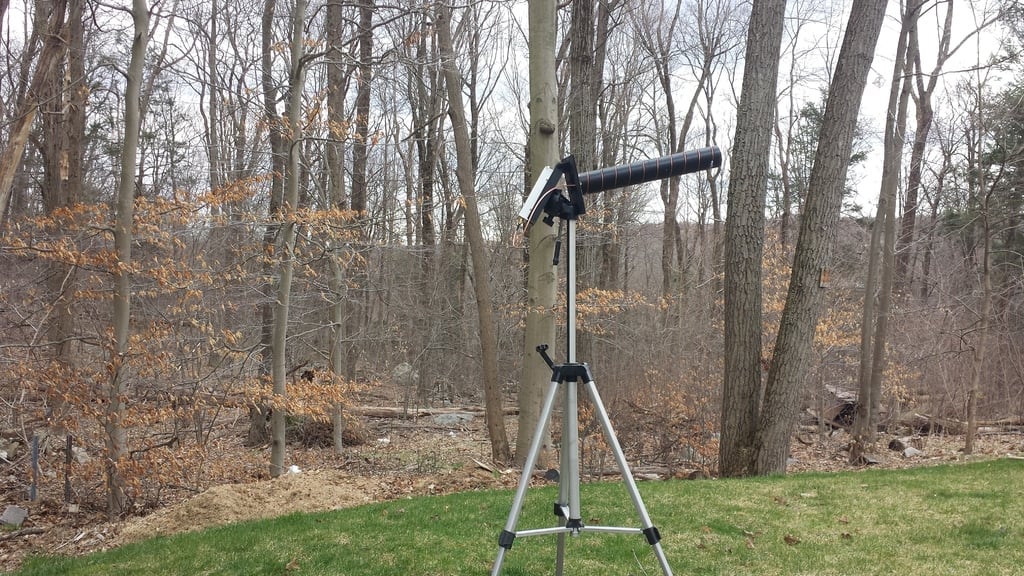
I designed this 2.4ghz helical beam antenna for my 2.4ghz base station. I used a calculator to give me the specs of the coil. Then I designed the antenna mast and complimentary parts in cad. This way I could ensure the diameter, spacing etc. meets the specs of the antenna calc. The antenna is somewhere around 15dbi gain. The beam is somewhere in the middle between wide and narrow. I was shooting for something that would work without a tracker. FYI. I use a a 3d printed adapter called DeWatt here on thingivers to use a 12v Dewalt battery to power the receiver. Assembly: You will need some copper wire. I used #14 copper I salvaged from some romex. You need enough to make 10 turns. You will also need a copper board 120mm x 120mm. I used PCB material but you can use any kind of metal you have handy. You will need some coax and sma or rpsma depending on your receiver. You will need a receiver. You can use a module in a google set like fatshark, or you can use the one I have. It is the same one that can be found here https://www.getfpv.com/2-4ghz-a-v-receiver.html they are out of stock but this receiver can be found all over the net. you will also need CA glue for permanent assembly. you have to print each part, but 2 pcs. of the antenna mast as it takes 2 of these to make a full antenna. Assembly: 1) Assemble the antenna mast. take the 2 pcs. of mast, and the mast coupler, and use CA glue. Put glue on the coupler, and on the faces of the antenna and push them together. Let this dry. 2) Prep the ground plane. Take the copper board (120mm x 120mm) and drill a 10mm hole in the center. Next take the back plane backer, put the rivit through it. Then put the copper board on it and line everything up square. Mark the hole that is off set from the center. This is the hole for the coax connection. Drill at least a 3.5mm - 4mm hole. Take the rivit out for now. Optionally you can now glue the copper board into the back plane backer. Set aside and let dry. 3) Copper coil. Here is what I did. I took something that was smaller than the antenna mast, in my case, the handle on a leaf rake. I had a broken one, and I cut of the end. About 10". Drill a hole in the center of it that is slightly smaller than 1/4" as best you can. Then put a double sided lag screw, 1/4", or cut the hex head of a 1/4" lag screw. Put the lag screw into a drill and drive it into the broom handle. Drill a hole towards the base of th handle just big enough to put the wire in. Then spin the drill slowly, and using a pair of pliers, hold the copper wire tightly, but with enough slack to let it slip. and allow the coil to wrap tightly. You will need more than 10 wraps. I did at least 15. Next take the coil and turn it on the mast slowly. This will ensure a snug fit. Coil it all the way on. Make sure to leave a half a turn that you bend inward to fit into the capacitive tuning ring. Next, clip the coil 10 full turns from the beginning. 4) Optional - Gluing the swivel mount. If you want to glue the swivel mount to the ground plane backer: put CA glue on swivel mount face. Slide rivet through, and then through the ground plane backer. Line up the mount so that it is 90' vertical, and press together. Once the glue grabs, slide the rivet back out. 5) Assemble antenna: Take rivet, and put through swivel mount and ground plane backer. Slide the capacitive tuning ring and slide it over the rivet. Place some CA glue on end of rivet and push the mast on the rivet. Align the capacitive tuning ring so that it lines up with the end of the groove on the mast, so there is 1 half turn that is flat. The extra bit of copper coil needs to run in this groove to the end. Clip off excess at the end. 6) Coax: Slide coax through the small offset hole in the ground plane backer. Strip about 1/2" of the outer jacket of the coax. Peel back shielding and twist it together off the side. Then strip about 1/4" of the center hot. Solder the shielding to the ground plane copper board. Solder the hot to the end of the coil. (You should Align this when assembling.) Your antenna is built. 7) mounting on tripod. In the back of the receiver base is a hole that should have 1/4" thread that fits a tripod mount. I couldn't get it to printer great, but you can force it in once and it will thread in easy after that. Attach your tripod mount to the base. Then attach to tripod. Using the hinge pin slide it trough the swivel mount of the antenna and base. Then use the hinge pin rivet to lock it together. DONE. 4/05/2020 - First test: I tested this in my back yard. I didn't have a lot of room. Lots of trees, but it was a good first test. I flew about 250ft away. Not very far but I can say that there was no flicker or break up at all. Usually there is always some sort of breakup when changing directions. Nothing as long as I was out in front of it. Very clear video. I then flew toward the side of the antenna about 50 feet away from the side of the antenna. As soon as I got to almost 90' from the antenna, I almost lost all video. But once I went back a bit, video came back. So it is definitely directional. I did some quick direction changes and some rolls and the video was rock solid. I flew up about 100 feet, and came back down and the video was rock solid. So far it's working well. I will update with a more extensive range test.
With this file you will be able to print 2.4ghz helical high gain beam antenna. with your 3D printer. Click on the button and save the file on your computer to work, edit or customize your design. You can also find more 3D designs for printers on 2.4ghz helical high gain beam antenna..