3 Axis Gimbal
thingiverse
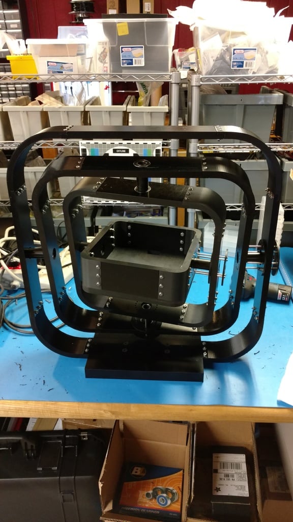
A 3 axis gimbal I designed for a test fixture at work. The original had printed corners and machined sides due to our printer not being large enough to print all the sides. I did a test print of the bearing hole in ABS with a 0.4mm nozzle and standard Fine settings in Cura 2.6 on our Ultimaker 2 and the bearing was a nice press fit. Stainless steel pins are used for the locking mechanisms. They were machined with grooves for 4 C-clips but I have listed external push rings which will work although you will only be able to install 3. Be sure to round off at least the one end of the pin so it will slide easily into the locking hole. Stick a block under the outer locking ring plate of sufficient height for the locking pins to clear the next ring by about an 1/8" and slide the inner locking ring up against the wall and seat in place with the external push rings. We reamed the locking pin holes to 0.128" and got a nice sliding fit which would stay back out of the way when in free swinging mode. We used slip rings from Adafruit to get power and data into the center. Assemble from the inside to outside (inside, middle, outer, outer #2). I used a washer on both sides of the joints for extra support. Use extra walls on the base so you can tap the 1/4-20 holes. I updated the parts list as I missed a couple parts were not stainless steel. EDIT 8/4/17: Added a D-Sub mount for a 15 pin D-sub connector. This is what I am using as part of the wiring system. You'll need longer screws where this mounts. I will post a picture soon of how I positioned them.
With this file you will be able to print 3 Axis Gimbal with your 3D printer. Click on the button and save the file on your computer to work, edit or customize your design. You can also find more 3D designs for printers on 3 Axis Gimbal.