3-bit Mechanical Punch Card Reader
thingiverse
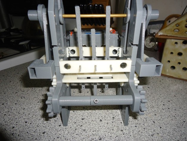
Assemble the punch card reader using the detailed instructions provided above. Print out necessary parts, attach them in order and load your program with laced punch cards. Ensure that the clearances are tight for optimal performance. Enjoy this 3-bit Jacquard-style all-mechanical punch card reader inspired by "The Mechanism of Weaving" textbook.
Download Model from thingiverse
With this file you will be able to print 3-bit Mechanical Punch Card Reader with your 3D printer. Click on the button and save the file on your computer to work, edit or customize your design. You can also find more 3D designs for printers on 3-bit Mechanical Punch Card Reader.