3-Phase Pulse Motor (Arduino Controlled)
thingiverse
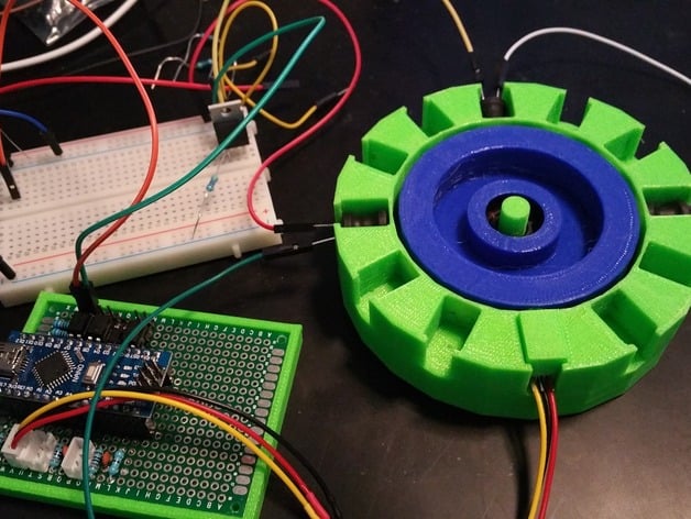
This is an excellent project for anyone seeking to build a simple Arduino-controlled 3-phase pulse motor with minimal engineering expertise required for initial setup. It's my second pulse motor, and I've incorporated some concepts I wanted to explore. The picture shows a single pole set up and it will run at reduced speed with just one pole. One great advantage of this design is that it doesn't require complex coil winding - off-the-shelf 9x12mm 10mH inductors are used, as shown in the photos. Each of these was measured at 14-15 ohms each and each pole consists of one hall sensor and three inductors wired in series. The coils should be driven from a 24V supply (12V won't be enough). Typical current draw was less than 250mA, but I tried so many different inductors that I lost track of the details. Magnets on the rotor are 1/2" x 1/4" N48 and are held in place by Gorilla-brand superglue. I recommend using the bottle with a brush applicator as it's easy to apply. Apply glue liberally, including over the outer face of the magnet to create a seal to help prevent the magnets from flying off. Perfect placement isn't very critical. You could probably use 6-7x 12mm x 1mm N35 magnets with no issues. The rotor spins freely on an ABEC-9 rated 608 bearing. The Hall switches are wired to signal the Arduino, which then turns on the mosfet isolated from the Arduino via an optocoupler. I made three JST female to female connector wires and stuck the hall switch in one end of the three-pin wire. I then bent the hall sensor pins to fit the plastic mounting pieces as shown in the photo. The circuitry is as simple as you'd expect, with very basic circuits that can be found posted everywhere. One note: Make sure your Arduino code incorporates a safety mechanism to shut off power after a short pulse. If you make the logic such that the hall being triggered = power being on as it might be if you wired it directly without an MCU then non-movement of the rotor would cause power to run continuously through the triggered pole and it will catch fire and melt if left in this state for too long. Being able to control timing and integrate safety features is part of the fun I had with this project. It may be possible to integrate an "auto" start routine, but I didn't bother and spun it manually to get it going. Here's my parts list: * 2 Batteries - 12V sealed lead acid connected in series for a total of around 25V when fully charged. * 9 Inductors - 9x12mm 10mH (25mH work too, but I think the 10mH worked better). * 1 608 skateboard bearing * 4 Magnets - 1/2in x 1/4in cylindrical neodymium * 3 Hall Switch ICs - I used OH 137 * 6 Mini micro JST 3pin - 3 PH and 3 XH preferably (see notes below) * 1 MCU - Arduino or other * 3 Mosfets - I used 200mH inductors that measured about 330 ohms as the "trigger coil." * Worked fine. TinkerCad links in case you want to tweak the design: Rotor: https://tinkercad.com/things/lES9LRQXVPK Stator: https://tinkercad.com/things/2yzUta3qp1s Hall Bracket: https://tinkercad.com/things/2d8KDFGzbsm Bedini SSG-style triggering circuits are possible, instead of a hall switch you'd use another 9x12mm inductor. I tested this with a 200mH inductor that measured about 330 ohms as the "trigger coil." Worked fine. I used two Mini Micro JST PH 3pin connector wires joined to form a complete female to female JST cable. Hall sensor went into one end and I soldered a male jst connector to my breadboard. At the time, I was pretty ignorant on JST connectors so I'll share what I know now. JST connectors come in different sizes (see: https://en.wikipedia.org/wiki/JST_connector). JST connectors larger/smaller than PH may not fit nicely in the hall bracket, but the PH do not like to fit on a standard 2.54mm pitch breadboard. So I recommend using one PH and one XH 3pin soldered together to form a single wire for the hall sensors. This will make your life easier.
With this file you will be able to print 3-Phase Pulse Motor (Arduino Controlled) with your 3D printer. Click on the button and save the file on your computer to work, edit or customize your design. You can also find more 3D designs for printers on 3-Phase Pulse Motor (Arduino Controlled).