3 way Smarthome ethernet and screw terminal relay case
thingiverse
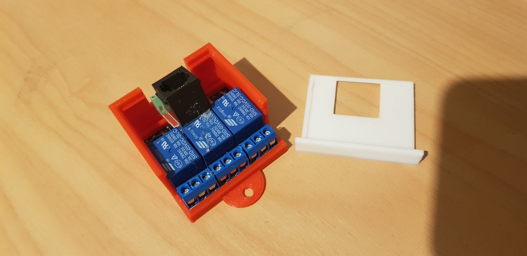
Human: Modified Version of My Previous Case with Three-Way Functionality. Used to house a modified three-channel, five-volt opto-isolated relay board similar to: https://www.aliexpress.com/item/32753936935.html Located in a wall behind an existing light switch or power point, either floating or screwed to a stud or frame. Existing 110/230v cables are connected to the relay output and switch the light or load. The five-volt control is via the Ethernet cable / GPIO or switched by the existing light switch. No neutral required because the control power is +5v via the ethernet cable. Solder an additional Ethernet connector with terminal block, providing a simple way to connect various sensors or the existing switch back to a GPIO controller. 1 x RJ-45 180-degree connector - https://www.aliexpress.com/item/32918645271.html 1 x RJ-45 breakout board - https://www.aliexpress.com/item/33031656602.html 1x 8-way 2.54mm pitch spring terminal block - https://www.aliexpress.com/item/32797749429.html The idea is based on a smart home model where transformers/voltage regulators and WIFI controllers are not located in the wall at the switch, but rather centrally in a metal fireproof enclosure. Plug in the Ethernet cable and switch the relay from GPIO or connect the original switch to override the lights ON locally. Can also be used in combination with capacitive touch sensors mounted on the back of a blank plate or RCWL-0516 motion detectors. The example shown is mounted on the back of a single light switch. 1 - 0v 2 - Vcc +5v 3 - 0v 4 - Relay3 5 - Relay2 6 - Relay1 7 - Spare 8 - Spare
With this file you will be able to print 3 way Smarthome ethernet and screw terminal relay case with your 3D printer. Click on the button and save the file on your computer to work, edit or customize your design. You can also find more 3D designs for printers on 3 way Smarthome ethernet and screw terminal relay case .