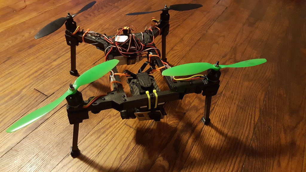
375mm folding quadcopter frame
thingiverse
All pieces are meant to be laid flat so that they are printed with the most strength possible. I've chamfered some bottom edges to make it easier to put together some of the piece as well. The holes on the front edge of the rear top plate are meant to hold the GPS and FPV antenna, the circle is the right size to fit a SMA connector while the other side planned to have another piece slide through and secured with a zip-tie to hold the GPS, however after making this one, I've decided to move those to another plate on the next version. The next version will likely have longer front arms, a thinner and shorter middle section, and a removable gimbal mount for storage and travel (for my model of gimbal, Tarot T4-3D, but hopefully can be adapted for others of similar size). Printing guide: Front Side Clip - 4x Front Top and bottom half plate - 2x normal, 2x mirrored Rear bottom plate - 1x Rear top plate - 1x Rear side - 2x Rear corner - 2x Landing gear side - 4x normal, 4x mirrored Landing gear foot - 4x Landing gear arm mount - 4x Landing gear blocker - 4x Motor top mount - 4x 15mm through mount - 4x 1x of each of the hole guides Hardware: 25x 25mm m3 screws 17x m3 nuts 4x 20mm m3 screws 4x m3 thumb nuts Carbon Fiber: 15x15 square tube: Front arms - 2x 80mm Back arms - 2x 130mm 10x10 quare tube: Body sides - 2x 165mm Body front - 1x 115mm Body back - 1x 95mm Landing gear - 4x 125mm Using hole guides: Front arms: Use motor hole guides on one end of the tube, drilling both holes vertically Use the Front Arm hole guide on the other end, drilling the first hole from the edge vertically, then the second hole horizontally The resulting holes should go (starting from the motor hole end) vertical, vertical, horizontal, vertical, see picture for reference Back arms: Use motor hole guides on one end of the tube, drilling both holes vertically Use the Rear Arm hole guide on the other end, drilling the first hole from the edge horizontally, then the second hole vertically The resulting holes should go (starting from the motor hole end) vertical, vertical, vertical, horizontal, see picture for reference Body front and back: Use 10mm hole guide on both ends, drilling only the first hole from the edge vertically on both Body front: Drill a hole in the center vertically (I ended up using the top plate to line this one up) Body sides: Use 10mm hole guide on both ends, drilling only the first hole from the edge vertically on both Use the second hole on the 10mm guide on only one end, drilling horizontally Landing gear: Use 10mm hole guide on one side, drilling only the girst hole from the edge vertically Assembly: The main things to note are that you will want to snap together any printed pieces before anything screws are secured and the landing gear are attached using the same screws that hold the motors in place. Any pieces that snap together are then sandwiched with screws, so putting in a screw first may mean disassembling something. Each of the pieces fit together as shown in the screenshots and pictures. The print was designed with very tight tolerances, so you may have tweak a little if your printer isn't very accurate for the pieces that snap together, but they're intended to be pretty secure when connected. I ended up using a rubber mallet on a few to get them together. My recommendation is in the following order: Snap together the front plate and clip pieces, then connect and secure in the 10mm front and side body tubes using 25mm screws Snap together the rear plate, side, and corner pieces, then connect and secure the 10mm front and side body tubes using 25mm screws vertically and 20mm screws horizontally Take each of the arms, you should have 1 horizontal set of holes in each. Drop a 15mm through mount into the arm, then get the hole lined up with the horizontal hole in the arm and screw a 20mm screw through until it is completely tight against the mount and one end is stick out of the arm not connected to anything (this will be used to secure the arms when unfolded). Secure each of the arms, making sure the screws we just put through line up with the holes in the sides of the frame. Now start on the landing gear; put the Motor top mount on the top and the Landing gear arm mount on the bottom of an arm, then start a 25mm screw through from the bottom. Once it starts poking out of the top mount, put a motor on and finish securing to that. Once the mount is secured and fully tightened, then you can put on the landing gear sides and blocker, then secure a 10mm tube using a 25mm screw. Landing gear feet can be put on at any time and are just pushed into place. Landing gear stay in place just due to friction, so make sure those are well-secured. I don't yet have the thumb nuts to show the arms being secured, but should be easy enough to see what's intended; mine are currently just held in place with friction as well and seems to be more than enough anyways. Working on a new version, so sorry about the rushed instructions, but let me know if you have any questions on assembly.
With this file you will be able to print 375mm folding quadcopter frame with your 3D printer. Click on the button and save the file on your computer to work, edit or customize your design. You can also find more 3D designs for printers on 375mm folding quadcopter frame.