3d printed Dremel 395 CNC Mill
thingiverse
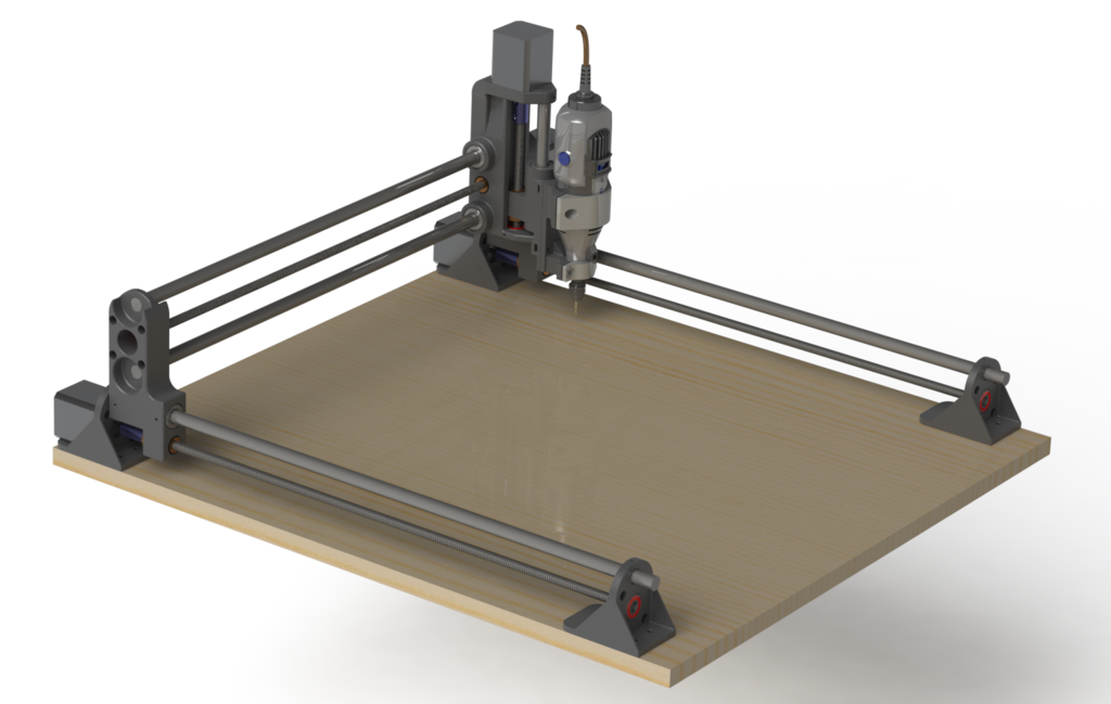
This is a redesign of Nikodem's DIY 3D printed Dremel CNC (originally for Dremel 3000): https://www.instructables.com/id/DIY-3D-Printed-Dremel-CNC 1st difference, this has a Dremel 395 mount as opposed to Dremel 3000. 2nd, the mount is now hinged, based on a Thingiverse model by “dintid”. https://www.thingiverse.com/thing:1761641 3rd, the mount is removable / replaceable, so I can easily swap in a pen or a laser etching module instead of the Dremel cutter. 4th, I got rid of the square 20mm extrusion frame. From what I can tell it doesn’t do anything better than the MDF base, so it’s wasted money and effort. I just build the gantry, and use that to align & locate the bottom four feet. 5th, I changed both X and Y leadscrews to 500mm length. Both axes achieve about 465mm travel now (the axial travel is optimized to be about 93% of the total screw length). 6th, I doubled up the linear bearings on the X, Y, and Z axes, for greater support (the Y axis is the two bottom parallel rails, the X axis is the gantry, the Z axis is the spindle plunge). There are 10 linear bearings total. Note: the linear bearings are high-precision parts. The only way to install them back-to-back is if the holes are honed, otherwise they are inevitably misaligned ever so slightly, causing them to drag fiercely on the 12mm rods. But you cannot hone a 3d print, so I had to back off my ambitions. Instead of 10 bearings I only used 5, but I put them at furthest distance so they had greatest stability. 7th, I changed from ordinary leadscrews to anti-backlash leadscrews. They are just slightly more expensive but make the machine that much more accurate and repeatable. Note: I also changed them from 8mm lead to 2mm lead. I also changed the motor drivers from 16th microstepping to quarter microstepping (still 400 microsteps per mm travel). The reason for this, high microstepping really kills the torque that the motors can deliver. By having 2mm lead though the motors turn 4x as much to move the same distance, which can be slower. I found Nikodem's feedrate estimates of 800 mm/min to be pretty crazy, it was breaking my mill bits left & right. I have to cut much slower than that (like 200 mm/min if not 100 mm/min). 8th, I revised the Z axis to be a single 12mm linear rod, so the carriage can become narrower. 9th, the Z axis now has a total range of 65mm. The bit goes no lower than the base, and no higher than the bottom of the gantry. This is so that the bit can’t go low enough to damage the base, and also so that the gantry clears a workpiece up to a 65mm tall. (This is with standard 3.175mm Dremel mills that are 38.1mm long, bottomed in the chuck). Ok another note. I included the 3d printed coupling model, which is just a solid coupling, but I have found these don't work well. My photos show solid aluminum couplings, they perform even worse. The screw shafts are always slightly warped and misaligned with the consequence that they wobble enormously where they connect to the motor. Just cutting a screw shaft releases internal stresses causing it to warp. So again I've had to face reality and buy compliant couplings. Don't bother printing the 5mm x 8mm couplings!
With this file you will be able to print 3d printed Dremel 395 CNC Mill with your 3D printer. Click on the button and save the file on your computer to work, edit or customize your design. You can also find more 3D designs for printers on 3d printed Dremel 395 CNC Mill.