3D printed kinetic Servo clock
thingiverse
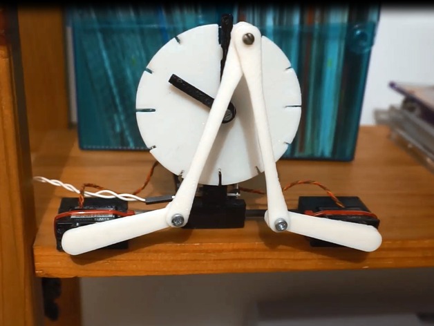
Somewhat based on, or inspired from, the excellent Plotclock (thanks Joo : http://www.thingiverse.com/thing:248009), here is my kinetic servo clock ! See it working here: https://youtu.be/nNygre-98G0 Motion is obtained from two RC servos whose arms are connected in a W shape. At the middle of the W sits a screw able to push the minutes arm via a pad. The minutes arm itself can push the hours arm ... An ESP8266 embeds all the needed software to make it a "smart clock" ! The ESP8266 is a wifi based microcontroller that can be easily programmed from an arduino IDE as if it was an arduino. The clock being connected to the internet (it's an IOT smart clock) it can get the time from an NTP server. The clock is then able to automatically set the arms at the right time, move the arms every minute and perform the adequate maneuvers to keep the arms in the right position. It is then really fun to see it doing its mesmerizing job. I must admit it is also a bit noisy, but so fun that you will forgive it! Obviously you need to build an ESP8266 board, but this is a piece of cake if you follow these step by step video instructions : https://youtu.be/Az-O-sgUcjM The software is provided in the files section. Sorry some comments are still in French. Some explanations are given here after... Enjoy ! Print Settings Printer: aerostock Rafts: No Supports: No Resolution: 0.2 mm Infill: 20% Notes: everything is printed in PLA How I Designed This Bill of materials Some black and white PLA 2x M3 screws; Length 1 cm 2x M3 screws; Length 2.5cm 7x M3 nuts A piece of bike inner tube or any flat and thin rubber 2x GWS pico servos (or any other but you'll have to adapt the support!) Distance between the two servos axis shall be 14cm sharp! One ESP8266 ESP-07 board 14cm of 4mm carbon tube (or any other material such as aluminium) The clock arms axis in details ... Positionning the clock arms by the servo and robotic arms is based on: Independancy of the 2 minutes and hours arms. When the minutes arm is moved, the hours arm stays in its position unless they both come in contact. Friction that will allow each arm to be moved when a small torque is applied, but force them to stay in position to avoid any rotation under gravity or vibrations... This friction aspect was the most critical to achieve. I ended with the following design (see macro picture): Punch a small hole into a piece of bike inner tube then cut around the hole a one cm round piece so that you end with a rubber washer. Cut two of them. Insert one inner tube washer into a 2.5cm M3 screw Insert the minute arm Screw a M3 nut and tighten it until there is enough friction to move the arm and keep it in position when gently shaked Deposit a tiny drop of CA glue to secure the nut and let it dry Once dry, insert the hours arm Insert the second washer Screw another nut and do the same tightening and gluing process Et voilà, you're ready Getting started with the arduino ESP8266 To upload the firmware into the ESP8266 you'll need to be familiar with arduino IDE environment. There are plenty good explanations on the internet. Just search for "arduino ESP8266". Assuming your environment and board are both ready to operate, you should be able to open the source code file and compile it. Uploading the firmware can be done two ways: Either by a serial upload using for instance a bluetooth JYMCU serial port. You'll need to do this way when programming the board for the first time. When done, open the serial monitor under arduino IDE and note the IP address of the board allocated by your internet router and displayed by the firmware. Or by the OTA (Over The Air) method... When the ESP board has been programmed, you noted the IP address of the board. Just open a browser and type in the address the IP address + ":85/update" (something like 192.168.0.71:85/update). And you should see an OTA webpage opening (see picture here after)... more explanation again on the internet (search for "ESP8266 OTA") Firmware users manual ... Basically there is nothing to modify in the firmware except few parameters to trim. The dedicated lines are all marked with a ""
With this file you will be able to print 3D printed kinetic Servo clock with your 3D printer. Click on the button and save the file on your computer to work, edit or customize your design. You can also find more 3D designs for printers on 3D printed kinetic Servo clock.