3D Printer Enclosure using 500mm square acrylic panel
prusaprinters
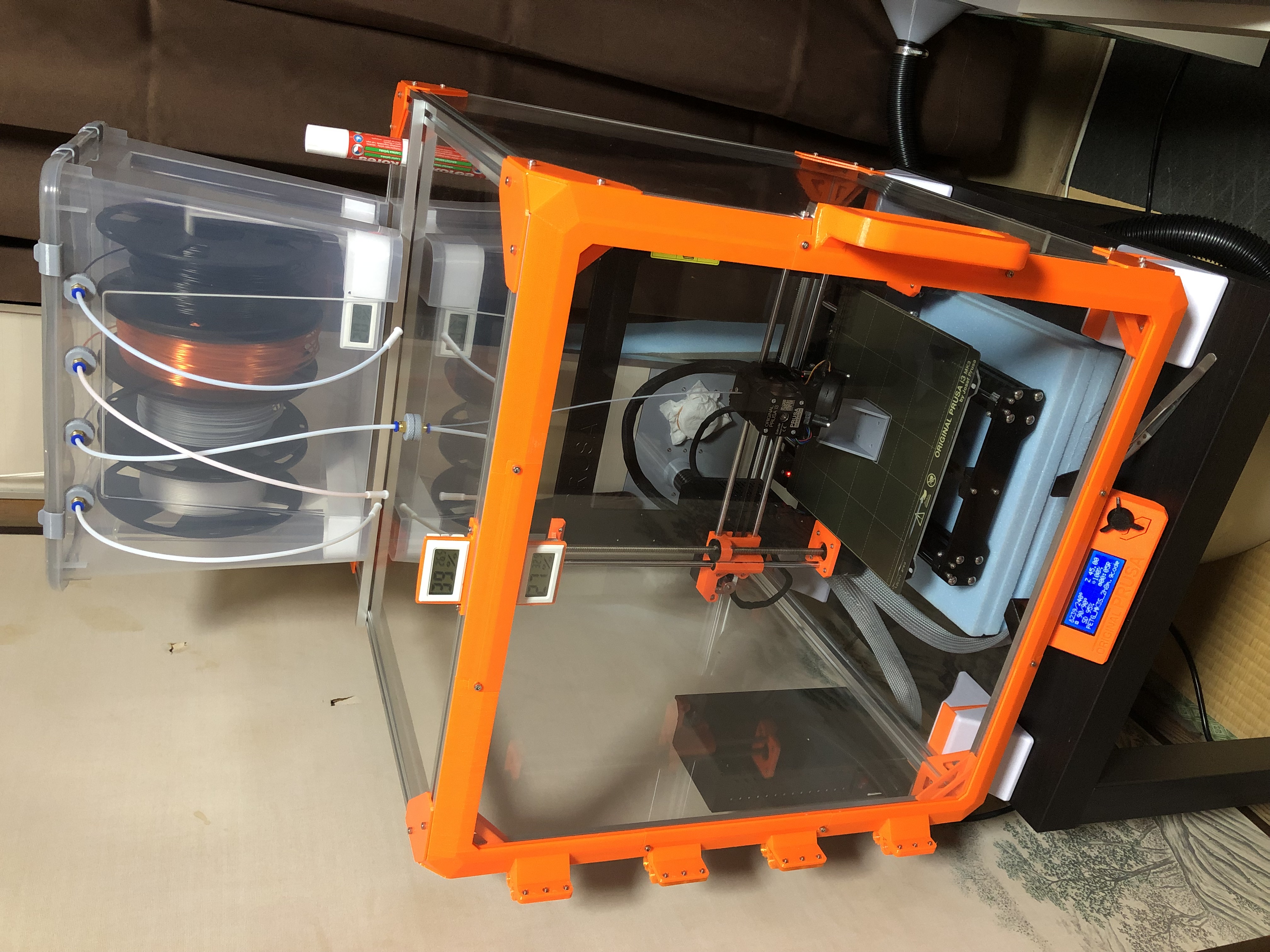
<p>I made an enclosure for a 3D printer using 500mm long 2020 aluminum extruded profiles and 500mm square acrylic panels for a partition. Below is a comparison with the enclosure using IKEA's LACK.<br>長さ500mmの2020アルミ押し出しプロファイルと、パーテーション用の500mm角アクリルパネルを使って、3Dプリンター用の筐体を作りました。以下はIKEAのLACKを使った筐体との比較です。</p><h3>Advantages<br>利点</h3><ul><li>Easy to operate PSU switches<br>PSUのスイッチを操作しやすい</li><li>Transparent top panel eliminates the need for LED lighting<br>天面パネルが透明なのでLED照明が不要</li><li>No need for special sized acrylic panels<br>特殊なサイズのアクリルパネルを必要としない</li><li>Slots in the extruded aluminum profile can be used to expand functionality<br>アルミ押し出しプロファイルのスロットを使って機能を拡張できる<ul><li><a href="https://www.printables.com/model/309337-stick-glue-holder-for-mounting-on-2020-size-alumin">https://www.printables.com/model/309337-stick-glue-holder-for-mounting-on-2020-size-alumin</a></li><li><a href="https://www.printables.com/model/310182-scraper-holder-for-mounting-on-2020-size-aluminum-">https://www.printables.com/model/310182-scraper-holder-for-mounting-on-2020-size-aluminum-</a></li><li><a href="https://www.printables.com/model/311068-tweezer-holder-for-mounting-on-2020-size-aluminum-">https://www.printables.com/model/311068-tweezer-holder-for-mounting-on-2020-size-aluminum-</a></li><li><a href="https://www.printables.com/model/311963-filament-cutter-holder-for-mounting-on-2020-size-a">https://www.printables.com/model/311963-filament-cutter-holder-for-mounting-on-2020-size-a</a></li><li><a href="https://www.printables.com/model/312718-kimwipe-holder-for-mounting-on-2020-size-aluminum-">https://www.printables.com/model/312718-kimwipe-holder-for-mounting-on-2020-size-aluminum-</a></li></ul></li><li>Easy to resize<br>サイズ変更が容易</li><li>The printing process can be observed from directly above<br>真上から印刷している様子を観察できる</li></ul><h3>Disadvantages<br>欠点</h3><ul><li>High cost of parts<br>部品代が高い</li><li>Difficult to assemble (I have never built an enclosure using LACK, so this is an estimate)<br>組み立てが大変(LACKを使った筐体を作った事はないので推定です)</li></ul><h3>About acrylic panels<br>アクリルパネルについて</h3><p>The acrylic panels were adapted from those used for partitions. It is preferable to use ones without notches and with separate parts for the legs. I used the following. The thickness is 3 mm. At first I planned to use 6 panels, so I bought a set of 4 panels and a set of 2 panels, but in the end I needed 5 panels.<br>アクリルパネルはパーテーション用のものを流用しました。切り欠きがなく、足が別部品になっているものが望ましいです。私は以下のものを使いました。厚みは3mmです。最初は6枚使う予定だったので4枚セットと2枚セットを買いましたが、最終的に必要な枚数は5枚になりました。</p><ul><li><a href="https://www.amazon.co.jp/dp/B091SR5C17">https://www.amazon.co.jp/dp/B091SR5C17</a></li><li><a href="https://www.amazon.co.jp/dp/B091SW78SJ">https://www.amazon.co.jp/dp/B091SW78SJ</a></li></ul><p>I think it would be easy to remix the enclosure with different sizes by replacing some of them with 500mm x 600mm or 600mm x 600mm acrylic panels and 600mm long aluminum extruded profiles.<br>一部を500mm x 600mmや600mm x 600mmのアクリルパネルと長さ600mmのアルミ押し出しプロファイルに置き換えれば、筐体のサイズを変更したリミックスが容易にできると思います。</p><h3>Processing of Acrylic Panels<br>アクリルパネルの加工</h3><p>The four corners of the acrylic panel are sandwiched and secured from both sides, eliminating the need to process the panel. Both the aluminum extruded profile and the acrylic panel are 500 mm, but there is an error in the dimensions of each, so please make adjustments while assembling. If you tighten the screws too tightly at the beginning, the panels may not fit together at the end.<br>アクリルパネルの四隅を両面から挟み込んで固定することで、パネルの加工を不要にしています。アルミ押し出しプロファイルとアクリルパネルはどちらも500mmですが、それぞれの寸法には誤差があるので調整しながら組み立てて下さい。最初にきつくネジを締めてしまうと、最後にパネルが嵌まらなくなる可能性があります。</p><p>The front door is made of printed parts and fitted into the frame, so there is no need to modify the panel. 2mm was used to stretch the panel because a gap was created when the panel was actually made to the exact size on the CAD.<br>正面の扉は印刷部品で枠を作って嵌め込んでいるので、これもパネルの加工は不要です。CAD上でピッタリのサイズにすると、実際に作った時に隙間が生じたので2mm伸ばしています。</p><p>The doors could not be made to open both ways because I could not find 250mm x 500mm panels. The doors are heavy and tend to deform under their own weight, so I used geared hinges. This was remixed to fit the 2020 aluminum extrusion profile.<br>250mm x 500mmのパネルが見つからなかったので、扉を両開きにする事はできませんでした。扉が重くて、自重で変形してしまいがちなのでヒンジにはギア付きのものを使っています。これは2020アルミ押し出しプロファイルに合うようにリミックスしました。</p><ul><li><a href="https://www.printables.com/model/294126-extended-tab-mini-gear-hinge">https://www.printables.com/model/294126-extended-tab-mini-gear-hinge</a></li></ul><h3>Processing of the top panel<br>天面パネルの加工</h3><p>In order to place the filament dry box at the top of the enclosure, I made a hole in the top panel for the filament to pass through. This hole is not necessary if the dry box is not used, but since there is no room in the height of the enclosure, some kind of device will be needed if the filament is to be placed inside.<br>上部にフィラメントドライボックスを配置するために、天面パネルにフィラメントを通す穴を空けています。この穴はドライボックスを使わない場合は不要ですが、筐体の高さに余裕がないので、フィラメントを内部に配置する場合は何らかの工夫が必要でしょう。</p><p>M6 holes are drilled in the center. The following parts are used to attach the pneumatic fittings.<br>M6の穴を中心に開けました。空気圧フィッティングを取り付けるために以下の部品を使っています。</p><ul><li><a href="https://www.printables.com/model/34472-knurled-pc4-m6-ptfe-drybox-feeder">https://www.printables.com/model/34472-knurled-pc4-m6-ptfe-drybox-feeder</a></li></ul><figure class="image image_resized" style="width:50%;"><img src="https://media.printables.com/media/prints/297784/rich_content/6ad57132-f855-4def-86ba-85ca3cf4f50d/img_0618.jpeg#%7B%22uuid%22%3A%22444c7b04-4192-4c61-b591-31abb88fba37%22%2C%22w%22%3A4032%2C%22h%22%3A3024%7D"></figure><h3>Transformation of the top panel<br>天面パネルの変形</h3><p>When I placed the filament dry box on top of the enclosure, the top panel flexed a lot. As a stopgap measure, I placed an aluminum square pipe. This will be addressed in the future, including fixing the filament dry box.<br>上にフィラメントドライボックスを乗せたところ、天面パネルが大きく撓んでしまいました。応急処置としてアルミの角パイプを置いています。これはフィラメントドライボックスの固定も含めて、今後対処するつもりです。</p><h3>Floating the enclosure<br>筐体を浮かせる</h3><p>The legs used to stand the acrylic panel up to make a partition were used as feet for the enclosure, as the height was just right for placing the LCD display at the bottom of the enclosure. If you cannot obtain these feet, you will need to make your own. I have not checked, but if you leave the LCD panel attached to the printer, the Y-carriage may collide with the enclosure because of the 500 mm internal dimensions of the enclosure.<br>アクリルパネルを立ててパーテーションにするための足は、高さが液晶ディスプレイを筐体下部に配置するのにちょうどよかったので、筐体の足として使っています。この足を入手できない場合は自作が必要です。確認していませんが、液晶パネルをプリンターにつけたままにすると、筐体の内部寸法が500mmなのでYキャリッジが筐体に衝突する可能性があります。</p><p>Even if you replace the heat bed cable cover with one that has a 60 degree angle below, there is still a risk of collision.<br>ヒートベッドケーブルのカバーを、以下の角度が60度のものに交換したとしても衝突する危険があると思います。</p><ul><li><a href="https://www.printables.com/model/88740-60deg-heatbed-cable-cover">https://www.printables.com/model/88740-60deg-heatbed-cable-cover</a></li></ul><h3>Removing the bottom panel<br>底面パネルの削除</h3><p>At first I had an acrylic panel on the bottom, but removed it because the vibration of the printer was transmitted to the enclosure and caused noise. Instead, I cut 15 mm thick styrofoam into 300 mm x 360 mm pieces, stacked four of them, and placed them under the printer. This is based on the following article.<br>最初は底面をアクリルパネルにしていたのですが、プリンターの振動が筐体に伝わって騒音が発生したので外しました。代わりに厚さ15mmのスタイロフォームを300mm x 360mmの大きさに切断し、4枚重ねてプリンターの下に敷いています。これは以下の記事を参考にしました。</p><ul><li><a href="https://help.prusa3d.com/article/vibration-when-printing-mk3s-mk2-5s_2177">https://help.prusa3d.com/article/vibration-when-printing-mk3s-mk2-5s_2177</a></li></ul><figure class="image image_resized" style="width:50%;"><img src="https://media.printables.com/media/prints/297784/rich_content/3442b69e-056f-4511-9730-1c51a5ee2fdf/img_0619.jpeg#%7B%22uuid%22%3A%22647e6731-def3-4eb7-b256-0969a88986a6%22%2C%22w%22%3A4032%2C%22h%22%3A3024%7D"></figure><h3>T slot nut adapter</h3><p>I wanted to be able to fit the nuts without using screws because of the large quantity used, but it did not work. If you know of a good T slot nut model, it would be better to use that.<br>使用数量が多いのでネジを使わずにナットを嵌め込めるようにしたかったのですが、うまくいきませんでした。良いTスロットナットのモデルを知っているのであれば、そちらを使った方が良いでしょう。</p><p>I placed them horizontally and printed them with support, but it was difficult to remove the support. It might have been better to place them at an angle like the model below. It still requires post-processing, but it seems easier than removing the supports.<br>水平に配置してサポート付きで印刷したのですが、サポートの除去が大変でした。以下のモデルのように斜めに配置した方が良かったかもしれません。後加工が必要なことに変わりはありませんが、サポートの除去より楽のような気がします。</p><ul><li><a href="https://www.printables.com/model/129445-t-slot-nut-m3-for-alu-2020-v-slot">https://www.printables.com/model/129445-t-slot-nut-m3-for-alu-2020-v-slot</a></li></ul><h3>Parts List<br>部品リスト</h3><h4>Required Parts<br>必須部品</h4><h5>Purchased parts<br>購入部品</h5><ul><li>2020 aluminum extruded profiles 500 mm long: 12<br>長さ500mmの2020アルミ押し出しプロファイル:12本<br><a href="https://www.amazon.co.jp/dp/B072VHZ8WM">https://www.amazon.co.jp/dp/B072VHZ8WM</a></li><li>acrylic panels of 500 mm square: 5<br>500mm角のアクリルパネル:5枚</li><li>Magnet catches: 2<br>マグネットキャッチ:2個<br><a href="https://www.amazon.co.jp/dp/B002A5NHTE">https://www.amazon.co.jp/dp/B002A5NHTE</a></li><li>M3x8mm screws</li><li>M3x6mm screws</li><li>M3 nuts</li></ul><h5>Printed parts<br>印刷部品</h5><ul><li>inner L angle: 24</li><li>outer corner cover: 16</li><li>corner block: 8</li><li>foot connecter: 4</li><li>corner frame: 2</li><li>corner frame left bottom: 1</li><li>corner frame left top: 1</li><li>straight frame: 2</li><li>handle frame: 1</li><li>hinge frame: 1</li><li>extended tab mini gear hinge: 4</li><li>LCD panel attachment: 1</li><li>LCD panel attachment mirror: 1</li><li>PSU attachment: 1</li><li>T slot nut adapter: 109<ul><li>inner L angle: 24x2</li><li>outer corner cover: 16x2</li><li>foot connecter: 4x1</li><li>extended tab mini gear hinge: 4x3</li><li>LCD panel attachment and mirrir: 1+1</li><li>PSU: 2</li><li>PSU attachment: 1</li><li>magnet catch: 2x2</li><li>thermo meter holder: 1x2</li><li>inner meter holder: 1x2</li></ul></li></ul><h4>Optional parts<br>オプション</h4><h5>Purchased parts<br>購入部品</h5><ul><li>Thermometer<br>温度計<br><a href="https://www.amazon.co.jp/dp/B09HS2GNBB">https://www.amazon.co.jp/dp/B09HS2GNBB</a></li></ul><h5>Printing parts<br>印刷部品</h5><ul><li>thermo meter holder: 1</li><li>inner meter holder: 1</li></ul><h3>How to assemble<br>組み立て方</h3><h4>Insert M3 nut into T-slot nut adapter<br> TスロットナットアダプターにM3ナットを挿入する</h4><p>There are many adapters, but be patient.<br>アダプターの数が多いですが、気長にやりましょう。</p><figure class="image image_resized" style="width:50%;"><img src="https://media.printables.com/media/prints/297784/rich_content/6e259699-8b16-4b83-aece-777a1ee1329a/img_0585.jpeg#%7B%22uuid%22%3A%2279579f91-eb0b-4aec-8066-ab337158b10f%22%2C%22w%22%3A4032%2C%22h%22%3A3024%7D"></figure><p>The basic idea is to insert 8 T-slot nuts at each end of the four slots in the extruded aluminum profile. This is for the "inner L angle" and "outer corner cover". Based on this condition, the number can be increased or decreased depending on the location. For example, since "outer corner cover" is not used on the front and bottom, the number is reduced by that amount.<br>Tスロットナットはアルミ押し出しプロファイルの四つの溝の両端に計8個挿入するのが基本です。これは"inner L angle"と"outer corner cover"用です。この状態をベースに、場所に合わせて数を増減していきます。例えば正面と底面には"outer corner cover"を使わないので、その分だけ数を減らします。</p><ul><li>bottom-front: 8<ul><li>outer corner cover: -4</li><li>LCD panel attachment and mirror: +2</li></ul></li><li>bottom-back: 8<ul><li>outer corner cover: -2</li></ul></li><li>bottom-left: 8<ul><li>outer corner cover: -2</li><li>foot connecter: +2</li><li>PSU: +2</li><li>PSU attachment: +1</li></ul></li><li>bottom-right: 8<ul><li>outer corner cover: -2</li><li>foot connecter: +2</li></ul></li><li>side-front-left: 8<ul><li>outer corner cover: -2</li><li>extended tab mini gear hinge: +12 or magnet catch: +4</li></ul></li><li>side-front-right: 8<ul><li>outer corner cover: -2</li><li>magnet catch: +4 or extended tab mini gear hinge: +12</li></ul></li><li>side-back-left: 8</li><li>side-back-right: 8</li><li>top-front: 8<ul><li>outer corner cover: -2</li><li>thermo meter holder: +2</li><li>inner meter holder: +2</li></ul></li><li>top-back: 8</li><li>top-left: 8</li><li>top-right: 8</li></ul><h4>Assembling the bottom and top frames<br>底面と天面のフレームを組み立てる</h4><p>Connect the four extruded aluminum profiles using "inner L angle" and "corner block". Do not tighten the screws at the beginning, but fix them temporarily.<br>"inner L angle"と"corner block"を使って4本のアルミ押し出しプロファイルを接続します。ネジは最初からきつくしめず、仮固定しておきます。</p><figure class="image image_resized" style="width:50%;"><img src="https://media.printables.com/media/prints/297784/rich_content/fa270031-bc51-43bf-9001-158e889e7444/img_0587.jpeg#%7B%22uuid%22%3A%22562d8c26-d718-4206-b6d9-8beb975bdcea%22%2C%22w%22%3A4032%2C%22h%22%3A3024%7D"></figure><p>Make two frames, one for the bottom and one for the top.Do not forget to insert the required number of T-slot nuts beforehand. The "corner block" is fragile and should be handled with care.<br>底面と天面用として二つのフレームを作って下さい。あらかじめ必要な数のTスロットナットを挿入しておくのを忘れないでください。"corner block"は折れやすいので、取り扱いに注意して下さい。</p><h4>Attach the feet<br>足を取り付ける</h4><p>Insert the "foot connecters" into the feet provided with the partition.<br>“foot connecter”をパーテーションに付属している足に差し込みます。</p><figure class="image image_resized" style="width:50%;"><img src="https://media.printables.com/media/prints/297784/rich_content/d4577bbe-75f7-400e-bfb6-3bd14863999f/img_0549.jpeg#%7B%22uuid%22%3A%22f7c63664-0b83-4e0d-a452-24fb15b88812%22%2C%22w%22%3A4032%2C%22h%22%3A3024%7D"></figure><figure class="image image_resized" style="width:50%;"><img src="https://media.printables.com/media/prints/297784/rich_content/557a1486-2aa3-495e-bb9f-0162461c1642/img_0548.jpeg#%7B%22uuid%22%3A%22f9f2f172-6dc2-43fe-9a8c-c45d27190c01%22%2C%22w%22%3A4032%2C%22h%22%3A3024%7D"></figure><p>Then attach them to the bottom frame.<br>そしてそれらを底面フレームに取り付けます。</p><figure class="image image_resized" style="width:50%;"><img src="https://media.printables.com/media/prints/297784/rich_content/cc34bfd9-8c13-4ec0-8950-c8d05356eb94/img_0588.jpeg#%7B%22uuid%22%3A%2271e0550c-c1cf-4433-904d-4c4f4b03eb09%22%2C%22w%22%3A4032%2C%22h%22%3A3024%7D"></figure><h4>Assemble the side frames<br>サイドフレームを組み立てる</h4><p>Connect the four aluminum extruded profiles using the "inner L angle". Then insert the necessary T-slot nuts in their respective places.<br>“inner L angle”を使って4本のアルミ押し出しプロファイルを接続します。その後、それぞれの場所に必要なTスロットナットを挿入して下さい。</p><figure class="image image_resized" style="width:50%;"><img src="https://media.printables.com/media/prints/297784/rich_content/4889e424-b5f8-4890-a5db-571d5ad30905/img_0589.jpeg#%7B%22uuid%22%3A%227114f187-dba1-4ad3-b3a1-8a32deefe12d%22%2C%22w%22%3A4032%2C%22h%22%3A3024%7D"></figure><h4>Attach the top surface frame<br>天面のフレームを取り付ける</h4><p>Attach the top surface frame that was assembled first. The number of T-slot nuts required depends on the location, so be sure to orient them correctly.<br>最初に組み立てておいた天面のフレームを取り付けます。場所によって必要なTスロットナットの数が異なるので、向きを間違えないでください。</p><figure class="image image_resized" style="width:50%;"><img src="https://media.printables.com/media/prints/297784/rich_content/62e0c97c-fa62-4593-9a95-bc4dda845842/img_0590.jpeg#%7B%22uuid%22%3A%2248ca1367-4876-4a6d-b68f-e282240d5537%22%2C%22w%22%3A4032%2C%22h%22%3A3024%7D"></figure><h4>Assemble the door<br>ドアを組み立てる</h4><p>Screw the magnetic catch hardware into the “handle frame”. The screws are the ones that come with the magnetic catch. This picture is of an older version, so the shape will be slightly different from the latest version.<br>“handle frame”にマグネットキャッチの金具をねじ止めします。ネジはマグネットキャッチに付属しているものです。この写真は旧版のものなので、最新版とは形状が若干異なります。</p><figure class="image image_resized" style="width:50%;"><img src="https://media.printables.com/media/prints/297784/rich_content/d490fc6d-0fbc-4a16-a894-35e41c9a6bca/img_0594.jpeg#%7B%22uuid%22%3A%228d50a07d-94b1-4a56-95d0-917418dc9941%22%2C%22w%22%3A4032%2C%22h%22%3A3024%7D"></figure><figure class="image image_resized" style="width:50%;"><img src="https://media.printables.com/media/prints/297784/rich_content/622659b8-769b-41e3-9466-ce326177fe08/img_0595.jpeg#%7B%22uuid%22%3A%22ff79a101-e66e-4c81-9d97-09cc70b20f9f%22%2C%22w%22%3A4032%2C%22h%22%3A3024%7D"></figure><p>Fit the acrylic panel into the groove of the following parts. Use M3x6mm screws only for fixing this door frame.<br>以下の部品の溝にアクリルパネルを嵌め込みます。このドアフレームの固定だけM3x6mmのネジを使って下さい。</p><ul><li>corner frame left bottom</li><li>corner frame left top</li><li>corner frame</li><li>handle frame</li><li>hinge frame</li><li>straight frame</li></ul><figure class="image image_resized" style="width:50%;"><img src="https://media.printables.com/media/prints/297784/rich_content/ce33cc67-f330-4a11-9c6a-b57b8b75bb49/img_0601.jpeg#%7B%22uuid%22%3A%22129af2ce-0b21-41ca-8603-3c6a11e1089a%22%2C%22w%22%3A4032%2C%22h%22%3A3024%7D"></figure><figure class="image image_resized" style="width:50%;"><img src="https://media.printables.com/media/prints/297784/rich_content/90bfcdab-c949-425c-aedd-e6f619b1fcbe/img_0602.jpeg#%7B%22uuid%22%3A%224f403420-8857-4931-aebf-75cfbb4f7ad7%22%2C%22w%22%3A4032%2C%22h%22%3A3024%7D"></figure><p>Attach the door to the frame using the "extended tab mini gear hinge". Then attach the magnetic catch to the frame, aligning it with the hardware on the handle. I assembled mine with the hinge on the left and the handle on the right, but it can be reversed.<br>“extended tab mini gear hinge”を使ってドアをフレームに取り付けます。そしてマグネットキャッチをハンドルに取り付けた金具の位置に合わせてフレームに取り付けます。私はヒンジが左、ハンドルが右になるように組み立てましたが、逆にすることも可能です。</p><figure class="image image_resized" style="width:50%;"><img src="https://media.printables.com/media/prints/297784/rich_content/2b4d7416-cfc5-4e85-900a-59e3f9240d7e/img_0667.jpeg#%7B%22uuid%22%3A%2287f0b726-3879-4983-97dc-1670c76d7c71%22%2C%22w%22%3A3024%2C%22h%22%3A4032%7D"></figure><h4>Attach the acrylic panel<br>アクリルパネルを取り付ける</h4><p>Install the acrylic panel by sandwiching it between the "inner L angle" and the "outer corner cover". After adjusting the acrylic panel so that it fits into the "inner L angle" and "outer corner cover", fix the screws of the "inner L angle" and "outer corner cover".<br>"inner L angle"と"outer corner cover"で挟み込む形でアクリルパネルを取り付けます。アクリルパネルを嵌め込めるように調整した上で、"inner L angle"と"outer corner cover"のネジを最終的に固定して下さい。</p><h4>Install the PSU<br>PSUを取り付ける</h4><p>Remove the power supply unit from the printer and install a replacement frame. I used the following one, but use the one appropriate for your model.<br>プリンターの電源を取り外し、代わりとなるフレームを取り付けます。私は以下のものを使いましたが、自分の機種に合ったものを使って下さい。</p><ul><li><a href="https://www.printables.com/model/13490-prusa-i3-mk3s-black-psu-replacement-frame-brace-wi">https://www.printables.com/model/13490-prusa-i3-mk3s-black-psu-replacement-frame-brace-wi</a></li></ul><p>Attach the "PSU attachment" to the power supply. Then attach it with three screws as shown in the picture. After all, the "PSU attachment" is fixed to the same frame as the other two screws, so I don't think it is necessary to use it, but I put it on just in case. If you are concerned about it, please remix the screws so that they are attached to a different frame.<br>“PSU attachment”を電源に取り付けます。そして写真のようにネジを3個使って取り付けます。結局のところ“PSU attachment”は他の二つのネジと同じフレームに固定してしまっているので、なくても良い気がするのですが、念の為につけました。気になる方は違うフレームに固定するようにリミックスして下さい。</p><figure class="image image_resized" style="width:50%;"><img src="https://media.printables.com/media/prints/297784/rich_content/2d04df38-dcd0-4a09-acf7-1f01caff973d/img_0613.jpeg#%7B%22uuid%22%3A%22a8e11ffd-2ffe-41e6-b77b-b5e6eab24e8f%22%2C%22w%22%3A4032%2C%22h%22%3A3024%7D"></figure><figure class="image image_resized" style="width:50%;"><img src="https://media.printables.com/media/prints/297784/rich_content/f500e8a8-4164-44a2-91f5-ee2e3a469a72/img_0616.jpeg#%7B%22uuid%22%3A%22ab391337-d4ff-47f4-8b46-f17de94cd9ae%22%2C%22w%22%3A3024%2C%22h%22%3A4032%7D"></figure><h4>Installing the LCD panel<br>LCDパネルを取り付ける</h4><p>Disconnect the cables from the LCD panel and remove the panel from the printer frame, along with its supporting parts (lcd-supports). Then screw the "LCD panel attachment" and "LCD panel attachment mirror" to the lcd-supports. After putting the cables back in place, screw the "LCD panel attachment" to the bottom-front aluminum extrusion profile to complete the process. The following picture shows the view from the top after fixing.<br>LCDパネルのケーブルを外し、パネルをその固定部品(lcd-supports)ごとプリンターのフレームから外します。そして"LCD panel attachment"と"LCD panel attachment mirror"をlcd-supportsにねじ止めします。ケーブルを元に戻してからbottom-frontのアルミ押し出しプロファイルに"LCD panel attachment"をねじ止めすれば完成です。以下の写真は固定後に上から覗き込んだ様子です。</p><figure class="image image_resized" style="width:50%;"><img src="https://media.printables.com/media/prints/297784/rich_content/2f2716e5-64e6-4a8d-87a7-103bfc9cf785/img_0668.jpeg#%7B%22uuid%22%3A%22d175ce5e-6833-4740-9f1d-c43218a73c2d%22%2C%22w%22%3A4032%2C%22h%22%3A3024%7D"></figure><h3>Completion<br>完成</h3><p>The assembly of the enclosure is now complete.<br>これでようやく筐体の組み立てが完成です。</p><figure class="image"><img src="https://media.printables.com/media/prints/297784/rich_content/fa520bbd-aa72-4e06-80a0-5e533aea3e2a/img_0617.jpeg#%7B%22uuid%22%3A%222ad78488-3304-42f6-8ad0-c4d126a188e0%22%2C%22w%22%3A3024%2C%22h%22%3A4032%7D"></figure>
With this file you will be able to print 3D Printer Enclosure using 500mm square acrylic panel with your 3D printer. Click on the button and save the file on your computer to work, edit or customize your design. You can also find more 3D designs for printers on 3D Printer Enclosure using 500mm square acrylic panel.