3D printer filament spool holder, fully-printable
thingiverse
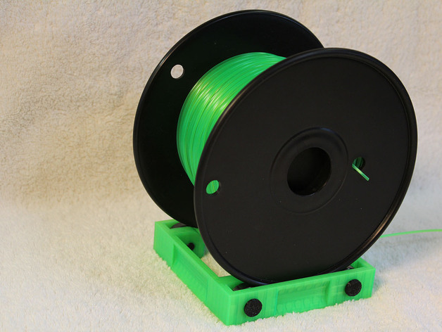
(UPDATED 2014-10-31, details at the end of this section) This spool holder design has a rectangular peripheral frame, supporting a filament spool's flanges on bearings or 3D-printed rollers. It is for use upright on a horizontal surface with a filament spool having intact rigid circular flanges. The design should not interfere with any filament which is below the height of the spool flanges, and if built using bearings it should have very low friction. The spool holder is designed to use four inexpensive 608ZZ shielded skateboard bearings ($1-2 each in quantity 8 or more). 3D-printed pins are used to secure the bearings in the frame; they should be 3D-printed at precise sizes, as they are intended to be a light (hand) press fit into the 8.00mm bearing bores and the frame. A design for bearing-sized 3D-printed rollers is included as well, which should be a loose low-friction fit on the pins; although bearings are preferable, these rollers may be adequate, at an even lower cost. When rollers are used rather than bearings, they are most likely to work satisfactorily where the filament is pulled off the spool nearly straight up or generally down, rather than mostly sideways. The designs are in OpenSCAD (SCAD files), and have a few feature switches, and are mostly parametric. To avoid binding, it is important that the spool flanges be a loose fit within the frame: 1-2mm of clearance in excess of the greatest width over the spool's flanges. Since the inexpensive 608ZZ bearings are only 7mm wide, each frame width is only suitable for a single width of spool. STL files are included for frames with two common widths, for 8" MakerBot spools (frame310, 3.10" inside frame width) and for 6" wiring-type spools (frame395, 3.95" inside frame width), but frames for spools of other widths or which are "virtually wider" due to warped flanges may easily be generated with OpenSCAD. Via parameters, the designs also could be customized for double bearings, or wider rollers, or to have the pin and bore diameters all in metric sizes (in case one has only metric drill bits). UPDATE 2014-10-31 A new version of the openSCAD source file for the frame, "frameV2.scad", has been uploaded. This version has some additional functionality, selectable via additional flags in the source. A few new ".stl" files have been uploaded; for other combinations of features or dimensions, one should expect to use openSCAD to generate customized ".stl" files for printing. Two new ".stl" files are intended to produce frames for use with MakerBot XL and XXL sized filament spools, and should be printable on MakerBot Replicator (dual) and Replicator 2-sized printers. Four other new (and more experimental) ".stl" files (with suffix "m" for Mini) are for various widths of 8" diameter filament spools, and are intended to be printable on 3D printers with small print beds, such as the MakerBot Mini. None of these frame sizes have been tested with rollers, and it is recommended that these only be built with bearings; this is due to the high spool weight of the XL and XXL spools, and due to the reduced bearing spacing to allow the small frames to be printed on 100mm printbeds. Instructions (UPDATED 2014-10-31; details at the end of this section) The pins should be 3D-printed two at a time, as provided in the SCAD and STL files. (Empirically, pins printed one at a time may have distortions from the plastic not cooling enough between layers and being dragged. When pins are printed four at a time, with a layer pattern A-B-C-D/D-C-B-A/A-B-C-D..., pins A and D come out with one diameter, and pins B and C with another. When pins are printed out two at a time, they seem to come out well and be the same size as each other, allowing a fairly precise and repeatable size to be achieved for a given combination of printer / filament / temperature / humidity / etc.) First print out a pair of pins, and determine whether they have the correct diameters. Ideally the 8mm part of the pins should be a light (hand) press fit in the the 8.00mm bore of a 608ZZ bearing. If your pins are not this size, slightly adjust the parameters for the pin diameters in OpenSCAD, perhaps by .05mm, and try again. Pins are likely to print out with their cross-sections being slightly eliptical, rather than round; this is probably OK, as long as they fit the bearing bore. Usable 608ZZ bearings should spin freely. If a bearing does not spin freely, it is possible that internal parts are dragging slightly on one or both of the shields. In that case, you could (by hand) press the bore sideways relative to the rest of the bearing, from both sides alternately, to see if it improves and becomes usable. Given the sometimes mixed reviews on the "$1" 608ZZ bearings, it may be worth purchasing a slightly better grade of bearing. The holes in the frame should only need light reaming, by hand (unpowered) with sharp drill bits and/or hand reamers. When doing this reaming, keep the bores of the holes coaxial (in line), rather than having a bit/reamer at an angle. After this has been done, a pin should be able to be pressed by hand into the frame and through the bearing, and should not fall out. An STL file has been provided for a test piece of just one corner of a frame, if desired to validate or adjust the sizing of the holes in the frame before taking the time to print out a full frame. There is very little "sanity checking" of the parameters, so be careful when modifying them. If rollers are used instead of bearings, their bores should be lightly reamed to remove any stray filament, which could cause substantial drag and resistance to rotating freely on the pins. The photographed spool holders and components were printed in ABS and PLA on MakerBot Replicator (dual) and Replicator 2 printers at TechShop Mid-Peninsula (San Carlos) and TechShop San Jose. MakerWare settings that have produced good results on those printers: for pins: .10mm layers, 3 shells, 20% fill for frames: .20mm layers, 2 shells, 20% fill; extended raft to minimize corners pulling up for rollers: .20mm layers, 2 shells, 20% fill; raft for consistent bore sizing on a heated bed Tools Required 1/4" (=6.35mm) conventional drill bit (not a brad-point drill bit) 5/16" (.3125") or 8mm (.3150") or letter-size "O" (.3160") conventional drill bit 8mm hand reamer (optional but recommended, ~$5 from Amazon) the tools should be sharp, and be careful to not cut yourself while "reaming"; holes should be "reamed" by hand power only, not with powered tools fine flat file (optional, for rollers: to smooth the raft-sides of the rollers as needed) UPDATE 2014-10-31 Pin diameters and frame widths may also be adjusted slightly by use of the scaling facility in MakerWare. Large adjustments would still need to be made in the source file and recompiled with openSCAD. Wider frames, especially the frame for 7" wide XXL spools, may require width adjustments to print in the correct size; with the spool flanges riding on bearings that are only 7mm wide, a fairly small percentage error in calibration could still be a problem. The XXL frame will need to be rotated in MakerWare (or other slicer) by 90 degrees around the Z axis to fit on moderate-sized print beds.
With this file you will be able to print 3D printer filament spool holder, fully-printable with your 3D printer. Click on the button and save the file on your computer to work, edit or customize your design. You can also find more 3D designs for printers on 3D printer filament spool holder, fully-printable.