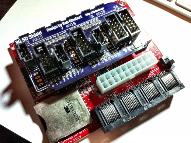
3G 5D Shield
thingiverse
Making those old red Gen3 motherboards more like a Gen4 motherboard. You can buy one in the MakerBot Store! http://store.makerbot.com/3g-5d-shield-for-cupcake.html This is a shield for the Gen3 Motherboard that allows connecting a fourth stepper (for controlling a stepper-extruder) directly to the motherboard. This is my "sorry guys" for coming up with the firmware changes and that ugly cable hack that was used to connect the Gen3 EC to an external stepper. Note: I fixed a glitch in the RPM variants of the Machines.xml files. Sorry about that. Below you can download a file "3G_5D_Profiles.zip" that contains three profiles: A skeinforge 40 profile, called "3G 5D (Dimension) Example v2," that is the same profile I use with both Gen3+Shield and Gen4 motherboards. Note that this profile is NOT for use the RPM variants of the machines files. Two skeinforge 35 profiles, called "3G 5D Shield (RPM) 1.75mm ABS MK7" and "3G 5D Shield (RPM) 1.75mm PLA MK7," that can be really be used with any stepper-driven extruder. These are for use with the RPM variants of the machine files. Update Oct 2nd, 2011: I just updated the hex file with endstop fixes. I also uploaded a new firmware based on 3.0 that will work better with RepG26. You will need to update the EC to 3.0 as well. The stock EC firmware will work. The source for the new 3.0 fimware is here: https://github.com/giseburt/G3Firmware/tree/3G-5D-Shield-3.0 Update Nov 4th, 2011: I've added an E-Stop connector and associated circuitry to make it reset the bot in case of a failure. Because of this I've changed the pricing slightly. Update Nov 13th, 2011: I've fixed a glitch in the 5D machines file for use with RepG27. Instructions Proper build instructions for the kits can be found at http://wiki.makerbot.com/3g-5d-shield 1) Solder all of the parts onto the shield -- there are 4 SMD parts that are fairly easy to solder, but are all optional. One of the SMD parts is the reset button, and since the shield covers the reset button on the motherboard I think you'll probably at least want that. The other three SMD parts are AND (or OR) gate chips for the endstops. (See notes about endstops below.) All of the rest of the parts are very simple-to-solder thru-hole parts. All of the headers go on the top, following the clearly marked solder mask, and all of the male headers go on the bottom. Endstop connectors are optional. (See notes about endstops below.) 2) Solder the female headers onto the Gen3 motherboard. (Did you even notice the place for them?) There will be three strips of 9-pins, one strip of 10-pins, and one 4-pin strip in the I2C area. You need to solder the header in the four I2C pins closest to the reset button. 3) Place the shield onto the motherboard, being careful to get all of the pins in place. Watch to make sure that the single "VCC" pin goes into the I2C VCC position okay. (The following instructions are MakerBot firmware/ReplicatorG-specific. RepRap firmware will need pin settings modifications, but should work just fine.) 4) Connect the power and FTDI cable, and upload the new firmware. (It's one of the files on this Thing.) 5) Place the 3G 5D Machines.xml file into your ReplicatorG/Machines folder. Open ReplicatorG and choose the 3G 5D () or 3G RPM () Driver that best suits your machine. The settings are all for Cupcakes, so you may have to modify for a Mendel or other type of machine. They are also all for Mk5/6-style extruders, and will need minor modification for other extruders. 6) Connect the X, Y, and Z stepper drivers to their marked positions. Connect the extruder stepper driver to the A position. If you are connecting to drivers that have 6-pin headers you can connect a 10-pin connector to the same cable. I have attached a photo showing how I did this. 7) Print! You will now be able to use most of the same settings in Skeinforge as you can with Gen4 hardware. You can chose 5D (with Dimension) or RPM (with Reversify). Make sure the driver you choose matches which type of gcode you want to generate. Notes About Endstops The Gen3 Motherboard uses almost all of the available pins. Driving a stepper motor requires three pins: Direction, Step, and Enable. After discussing it with several other MakerBotters and RepRappers, we concluded that the endstops are rarely used, and at least three them could be eliminated to make three pins available to drive a fourth stepper. So, that's exactly what I did. I rerouted three endstop connections (the max endstops) to drive a fourth stepper. But the more I thought about it, the more I thought that there's no need to lose those endstops. We can just route them to the same pins. So, X-Min and X-Max become the same signal. This requires some minor modifications to the firmware, but is otherwise not a problem. Well, except that some endstops (Gen4 mechanical endstops, for example) are use a normally High (+) signal to indicate not triggered. Which means if I simply tie two endstops together, when one gets triggered it will short out on the other one and shut the bot off. To solve this I came up with two options, both of which are on this PCB: 1) Use only Min endstops. Since the firmware sees them as both min and max they can really be at either end of the travel. 2) Use an AND chip (or an OR chip if your endstops are normally low) to tie the two signals together safely. The problem with this method is that it you don't have both endstops in place, then you have to tie one high somehow. The current version of the schematic doesn't handle this problem, so you have to put "fake" endstops in place. I'll update it soon to have pull-up resistors for the Max positions. With this PCB you can go with either solution. I suspect most people will not be using endstops, and those that are using endstops will only need one endstop for each axis. For the case where you only need one endstop per axis there's a simple solder-jumper for each axis that you can bridge with a lump of solder to directly connect the Min connection of each axis to the appropriate pin. Do not bridge these jumpers and install the AND chip. You will most likely permanently damage the chip. Alternatively you can solder the three AND chips in place. I'm using these chips here: http://octopart.com/sn74ahc1g08dbvr-texas+instruments-464404 Availability You can buy these in the Makerbot store! http://store.makerbot.com/3g-5d-shield-for-cupcake.html Source The firmware source is at https://github.com/giseburt/G3Firmware/tree/3G-5D-Shield I'll issue a pull-request with MakerBot once I clean it up to play nicely with the other firmware options. Ugly cable hack alternative Ok, for those of you that don't mind having an ugly cable hack, and you don't need endstops, you can make the following connections to make the 3G 5D Shield firmware work with a fourth stepper motor: Solder 0.1" female headers onto the long rows of pin connections on the Gen3 motherboard. We will connect to the pins that way. We only need the pins A0, A5, and 21. On the stepper driver it will have either a 10-pin or 6-pin connection. With the gap in the side of the header shield to your left when looking at either size of connector then pin 1 is the top left, pin 2 is top right, pin 3 is below pin 1, etc. All directions assume you're looking at it in this orientation. See http://wiki.makerbot.com/smd3 for a great illustration and explanation of the pins. Connect Pin 3 of the stepper driver, which is directly down one pin from the top-left pin, to the pin marked "21" on the motherboard. This is the STEP pin. Connect Pin 4 of the stepper driver, which is directly to the right of Pin 3 that we have already connected, to the pin marked "A5" on the motherboard. This is the DIR pin. Connect Pin 5 of the stepper driver, which is directly below Pin 3, to the pin marked "A0" on the motherboard. This is the ENABLE pin. Connect X, Y, and Z to their stepper drivers as you normally would. Notes: I haven't tested the cable hack. It's very important than you do not connect any max endstops when using a Gen3 stepper driver! It could release the blue smoke or short and burn a trace on the PCB, causing a fire and ... just don't do it! You can connect a "Max" endstop to the Min position of the Gen3 without any trouble, since Min and Max are now the same signal. For a great example of a cable, tim1986 posted a photo of the one he made: http://www.thingiverse.com/derivative:13984 If you do use the ugly cable hack method, please take a photo and post an I Made One! Enjoy!
With this file you will be able to print 3G 5D Shield with your 3D printer. Click on the button and save the file on your computer to work, edit or customize your design. You can also find more 3D designs for printers on 3G 5D Shield.