62-150mm variable macro extension tube (Canon EF/EF-S)
prusaprinters
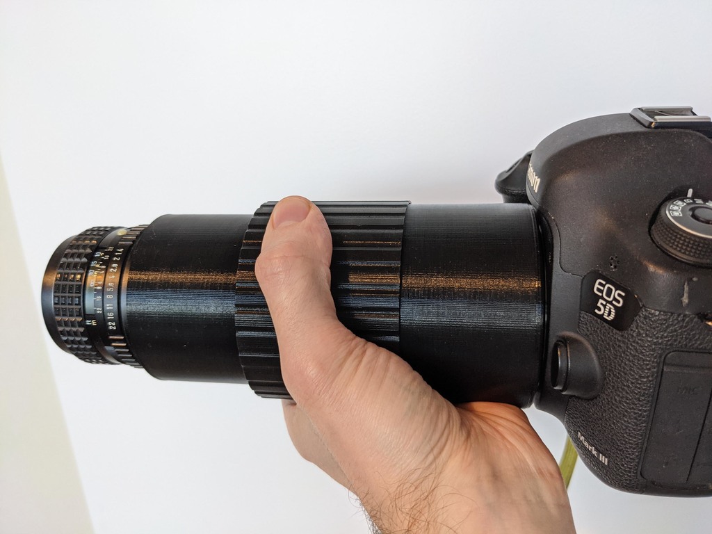
<p>This variable-length extension tube allows you to mount a Canon EF/EF-S lens to a Canon full-frame or crop camera. When you twist the middle section of the tube, it expands to vary between 62mm and 150mm of extension. When used with a 50mm lens this allows you to go from about 1.2x to 3x macro magnification (focusing to infinity is impossible).</p><p>I'm using a Pentax K lens with a metal lens adapter to Canon EF (various other lenses including Nikon can be adapted too).</p><p>Filament should be black PETG or similar (PLA likes to deform under pressure, which can loosen pieces over time). Please note that your PETG should be nice and dry to minimise stringing, since some of these strings would end up gumming up inaccessible threads.</p><p>TPU filament is required to print the spring for the Canon lens locking mechanism. I'm using Flexfill 98A.</p><p>Extra parts required:</p><ul><li>M3x50mm cap head screw x1</li><li>M3x8mm cap head screw (hex drive), black finish, x3</li><li>Hex driver tool to suit the M3x8mm screws (typically 2.5mm) with >=100mm long shaft, and ball end</li><li>M3 hex nut, any material x1</li><li>M3 hex nut, brass x1</li><li>M2x20mm countersunk screw x2</li><li>M2 hex nut x2</li><li><a href="https://www.amazon.co.jp/gp/product/B00MIA7EHC?tag=thingiverse09-20">M1.7x6mm plastic self-tapping screws x2</a></li><li>Silicone grease</li></ul><p><strong>Please note that the grease used in this tube is super not good if it comes into contact with optical elements like your lens or camera sensor. At the very least this will require a wet cleaning of your camera sensor, and in the worst case this will render your camera into scrap.</strong> Take care.</p><h3>Shooting with the tube</h3><p>To mount a lens to the tube, align the Canon lens' alignment mark with one of the two circles on the top of the printed mount (one for EF lenses, the other for EF-S lenses), and push the lens downwards slightly to push the lens locking plunger out of the way, then twist the lens onto the mount as normal. You may need to press upwards on the bottom of the 50mm lens locking bolt to return the locking plunger to the locked position (which prevents the lens from unscrewing).</p><p>To mount the tube to the camera, align the small circle mark on the outer edge of the tube's mounting face with the red dot on your camera's mount, and twist it on until the camera's lens locking pin engages.</p><p>You can twist the center section of the tube to collapse or extend it. The collapsed position corresponds to 62mm of extension, so if you're using a 50mm lens on the tube you will get at least 1.2x of magnification here. Max extension is 150mm, so you'll get at least 3x magnification. Shorter lenses give stronger magnification and longer lenses give weaker magnification.</p><p>To remove the lens from the tube, looking from the bottom of the tube, use pliers to pull downwards on the head of the 50mm locking screw, which will retract the lens locking plunger, then untwist the lens.</p><h3>Want to shoot with a Sony camera?</h3><p>I have a 0-35mm and 50-150mm version of this tube designed for Sony F/FE mount cameras instead if you like:</p><p><a href="https://www.prusaprinters.org/prints/143759-0-35mm-variable-extension-tube-for-wideangle-macro">https://www.prusaprinters.org/prints/143759-0-35mm-variable-extension-tube-for-wideangle-macro</a> - 0-35mm version<br><a href="https://www.prusaprinters.org/prints/143761-50-150mm-variable-macro-extension-tube-canon-efef-">https://www.prusaprinters.org/prints/143761-50-150mm-variable-macro-extension-tube-canon-efef-</a> - 50-150mm version</p><h3>More macro accessories</h3><p>To take most of the photos above I used my <a href="https://www.thingiverse.com/thing:4652788">Twin Loc-Line Arm Mount for Camera Tripod Sockets</a>, <a href="https://www.thingiverse.com/thing:3844481">Diffusers for Canon MT-24EX Macro Flash</a>, and <a href="https://www.thingiverse.com/thing:3785376">MT-24EX mount system for Loc-Line arms</a>.</p><h3>Print Settings</h3><p><strong>Printer Brand:</strong></p><p>Prusa</p><p><strong>Printer:</strong></p><p>I3 MK3S</p><p><strong>Rafts:</strong></p><p>No</p><p><strong>Supports:</strong></p><p>No</p><p><strong>Resolution:</strong></p><p>0.1</p><p><strong>Infill:</strong></p><p>10%</p><p><strong>Filament:</strong> Kiwi3D PLA White </p><h3>Post-Printing</h3><p>The STLs are arranged into three 3MF project files for PrusaSlicer: large parts, small parts, and the spring. I'll explain how the settings in these projects were customised so you can apply those to other slicers too.</p><figure class="image"><img src="https://media.prusaprinters.org/media/prints/143757/rich_content/dc7f3a33-ef72-42f3-b177-7adba69c46fe/large-parts-with-labels.jpeg#%7B%22uuid%22%3A%222fcc6a2c-1465-4fe1-bf42-4f87099e8737%22%2C%22w%22%3A1920%2C%22h%22%3A1684%7D"></figure><p><strong>Large parts</strong></p><p>These Large Parts need to be printed one-by-one, not all 4 at once. You can right-click the eye icon next to the remaining parts on the plate to disable them for printing.</p><p>In general, layer height is 0.1mm, filament is black PETG, supports for enforcers only, 2 perimeters, seam position random, infill 10% rectilinear.</p><p>On the "slip ring", a layer range from 0 to infinity has been added to override the layer height for this entire part to 0.2mm</p><p>The Body STL has the "body finger zone" added to it as a modifier region, with 8 perimeters set (this makes the region of the body with the two screwholes in it fully solid).</p><p>The little block in the Body with the two screwholes in it gets painted for support enforcement.</p><p>A layer range from 54.60mm to 61.00mm on the Body overrides the layer height for this region to 0.2mm. This encompasses the entire solid top of the mount, and in particular ensures that the blue bridging (shown below) that closes the top of the tube is printed at 0.2mm instead of 0.1mm (the 0.2mm bridges are more robust and fail less often):</p><figure class="image"><img src="https://media.prusaprinters.org/media/prints/143757/rich_content/cf61f6a8-3835-4f0b-b839-b34d407d6769/top-bridging.jpeg#%7B%22uuid%22%3A%22539f915c-9513-4a4e-8752-22cf086113d4%22%2C%22w%22%3A2280%2C%22h%22%3A1480%7D"></figure><p><strong>The bridging (blue) near the top of the Body object must be a 0.2mm layer</strong></p><figure class="image"><img src="https://media.prusaprinters.org/media/prints/143757/rich_content/699b5cee-2227-47bb-b5e4-7b3e25725e17/small-parts.jpeg#%7B%22uuid%22%3A%2269da3c50-e1d5-49ec-abc2-845b50973d14%22%2C%22w%22%3A1238%2C%22h%22%3A1166%7D"></figure><p><strong>Small Parts</strong></p><p>The three Small Parts shown above should be printed at 0.1mm layer height in PETG. Perimeters is 2. Infill needs to be 100%, except for the "door" STL (highlighted in green above) which can be printed at 20% rectilinear. Print all three at the same time.</p><p>A colour change has been added at 3.9mm, where you should unload the filament and install an M3 hex nut in the Plunger on the left. Verify that the top of the nut sits below the level of the surrounding plastic before reloading the filament to continue, otherwise the extruder could crash into it.</p><p>A second colour change has been added at 5.2mm, where you should unload the filament and add two M2 nuts into the two spaces in the Body Finger on the right (flat edges of the sides of the hex will face downwards).</p><figure class="image"><img src="https://media.prusaprinters.org/media/prints/143757/rich_content/e3044853-878f-42ac-89ad-0dd4de872af0/spring.jpeg#%7B%22uuid%22%3A%22349ad6f8-a219-4024-aeb2-b95adc2842c7%22%2C%22w%22%3A1244%2C%22h%22%3A1732%7D"></figure><p><strong>Spring</strong></p><p>This 30mm spring needs to be printed in flexible filament such as 98A Flexfill. Lots of custom settings are required here.</p><p>Starting with the 0.1mm DETAIL preset, Spiral Vase mode was turned on in the print settings. Top and bottom layers are set to 0. The stiffness of the spring can be tuned by changing the extrusion width, I set all of the extrusion widths down to 0.4mm from the default of 0.45mm.</p><p>I started with a filament profile of "generic FLEX", but big changes need to be made to the filament settings get enough cooling to be applied to each layer. Because each layer is so tiny and prints so quickly, if they are printed using the default settings the whole thing just melts and warps and there are severe gaps in the structure.</p><p>Set Keep Fan Always On, set the min fan speed to 100%, change "disable fan for the first" to "1 layers". On the advanced page, set max volumetric speed to 0.5mm^3/s (down from the default of 1.2mm^3/s) so that there is enough time for the layers to cool as they are laid down.</p><h3>Assembly</h3><p>Clean up any stringing or blobs on the large parts. I do this by very briefly waving a pocket butane torch near the print (a fraction of a second) which causes all the strings to shrivel up into little balls. These are then easily rubbed off the surface with a finger. Don't actually touch the flame to the print, or it'll melt and warp almost instantly.</p><p>On the Body piece, superglue the M3 brass hex nut into the slot pointed to by the red arrow below, and ensure it sits below the plastic surface (to avoid scratching your camera's mount). Pierce the bridge that is blocking the camera mount (shown below in blue) and clean up the resulting edge with a deburring tool or blade. I used superglue to stick down any bridge lines that were dislodged inside the body.</p><p>Apply silicone lube to the threads in the Body and screw that into the Middle and unscrew it a couple of times to distribute lube between these two pieces. Leave them disconnected when you're done. Mop up any squeeze-out with a paper towel.</p><p>Apply silicone lube to the threads in the outer perimeter of the Lens print (I used a toothpick to help me get it down into this slot). Note,<i>don't</i> apply any lube to the ribs in the inside ring of the Lens, this is not a thread, it is a light scattering baffle.</p><p>Thread the Lens part into the Middle to distribute lube like you did with the Body and Middle, and leave them separated when you're done.</p><figure class="image"><img src="https://media.prusaprinters.org/media/prints/143757/rich_content/9ebbb224-783b-4ce0-8d81-a813c5426848/body-preparation.jpeg#%7B%22uuid%22%3A%22fe93bfe7-160f-4815-876d-13a23cf7fd70%22%2C%22w%22%3A1920%2C%22h%22%3A1073%7D"></figure><p><strong>Nut to be added and blue bridge to be removed</strong></p><p>The Slip Ring is going to be installed into the Middle part using a hammer, and once this is installed it won't really be removable again, so let's get those mating surfaces ready now.</p><p>On the Slip Ring, ensure that on the outside of the part there are no blobs sticking to the surface (you can scrape it clean with a blade). On the Middle part check the same except on the inside. While you're here, make sure there are no debris stuck in the vertical channels in the inside of the Slip Ring.</p><p>Apply silicone lube to outside of the Slip Ring and inside of the Middle with a finger.</p><p>The image below shows how these two parts need to end up once the Slip Ring is installed. To install the Slip Ring, first ensure that each piece is oriented the correct way up. For the Slip Ring the blocked tops of the skinny slots needs to be uppermost (circled in red below). For the Middle piece the small vertical gap shown by the arrow at the top right of the image must be uppermost, or else the Middle will shatter during assembly.</p><p>Prepare a flat work surface and put the Middle piece onto it in the correct orientation (the base of the Middle must be fully supported to avoid it shattering). Place the Slip Ring on top of the Middle in the correct orientation, place something flat on top of it like a board, and tap this board with a hammer to slowly work the Slip Ring into the Middle piece, ensuring you do this evenly so it doesn't tilt too far over. Once fully installed you should be able to freely rotate the slip ring around inside the middle piece with your fingers. (Also double check that you didn't shatter the walls of the Middle piece during installation).</p><figure class="image"><img src="https://media.prusaprinters.org/media/prints/143757/rich_content/055e7459-77e0-432a-aa60-b38341094459/slip-ring-orientation.jpeg#%7B%22uuid%22%3A%22fc6dd8b4-3f7b-4504-8d27-e5914108026b%22%2C%22w%22%3A1920%2C%22h%22%3A1671%7D"></figure><p><strong>Slip ring installed into Middle piece</strong></p><p>For the Lens print, we'll prepare the Canon lens locking mechanism now.</p><p>Looking at the bottom of the Lens print, there are two 1.7mm screwholes that are covered by a sacrificial bridge, and need to be uncovered by poking them with a sharp object like a toothpick (red arrows below):</p><figure class="image"><img src="https://media.prusaprinters.org/media/prints/143757/rich_content/c3bfbfaf-5a5e-4207-b92c-1d017a7ef206/m17-screwholes.jpg#%7B%22uuid%22%3A%22a76f4eb3-311f-4ef0-a92b-e1a517e0eab3%22%2C%22w%22%3A1135%2C%22h%22%3A1080%7D"></figure><p>Looking at the top of the Lens piece, there will be some remnants of a bridge over the locking plunger slot (the triangles highlighted in blue below) which need to be torn out:</p><figure class="image"><img src="https://media.prusaprinters.org/media/prints/143757/rich_content/4a8789d5-db14-48b8-afe2-6c92ccb67e79/hole-bridge.jpeg#%7B%22uuid%22%3A%2274bca9ab-c014-4f3c-8b02-29ba052a5954%22%2C%22w%22%3A1123%2C%22h%22%3A1080%7D"></figure><p>Now we'll assemble the locking plunger assembly as shown below.</p><p>Thread the 50mm screw through the bottom of the door print. Onto the protruding threads add the spring. Screw the locking plunger (with its embedded M3 nut) onto the end of the thread, compressing the spring somewhat in the process. Avoid fully tightening this screw, because the screw would split the plunger in half or erupt out of the top of the plunger if you do (just thread it on until it reaches the end of travel).</p><p>Apply a little lube to the sides of the plunger, then push the whole locking assembly into its home in the Lens print. If the plunger refuses to pop out of the top of the Lens part, don't try to force it, this will cause the top of the Lens part to blow out and break (ask me how I know, lol). Instead clear any debris left in the gap in the Lens using a hobby knife or sharp tweezers until it can push through cleanly.</p><p>Secure the Door to the Lens using two M1.7 screws. You should now be able to grab the head of the 50mm screw with pliers to retract or deploy the locking plunger, work it backwards and forwards a few times to work out the kinks.</p><figure class="image"><img src="https://media.prusaprinters.org/media/prints/143757/rich_content/2fd25b9b-dac8-4345-a565-8aaba772a02e/locking-assembly-installed.jpeg#%7B%22uuid%22%3A%2259130fe5-be24-4b51-a9be-647007c2a26b%22%2C%22w%22%3A1920%2C%22h%22%3A1546%7D"></figure><p>In the next step we will attach the Body Finger to the Body piece using the two M2x20mm screws. In order to align this piece properly we'll first partially assemble the tube as shown below.</p><p>Partially screw the Lens piece into the Middle piece. You can only screw it in a fraction of a millimetre before the Lens Finger (red arrow below) will crash into the Slip Ring. At this point spin the slip ring until the Lens Finger drops into its slot in the Slip Ring:</p><figure class="image"><img src="https://media.prusaprinters.org/media/prints/143757/rich_content/c7e3bed1-0da2-4b56-9d94-02e3adb37f2c/lens-finger.jpeg#%7B%22uuid%22%3A%22de23b3c3-b10b-44cd-ad4f-39c6093f72e3%22%2C%22w%22%3A881%2C%22h%22%3A1080%7D"></figure><p>Continue screwing the the Lens piece (yellow) into the Middle piece (cyan) until it's mostly engaged, as shown below. Apply lube to the sides of the Body Finger (pink), then slide it up into its recess in the Lens tube:</p><figure class="image"><img src="https://media.prusaprinters.org/media/prints/143757/rich_content/ef876709-a8c1-4e7d-999c-2d7598f4c75a/finger-install-pt-1.jpeg#%7B%22uuid%22%3A%22746ba8ee-19a0-4e5b-9ce2-3c01257b7a4e%22%2C%22w%22%3A1920%2C%22h%22%3A1681%7D"></figure><p>Now screw the Body piece in from the bottom until the Body Finger (pink) lines up with the corresponding screwholes in the Body, the Lens and Body pieces are fairly close to each other, but you are still able to grab onto the bottom of the Body Finger to pull it downwards to meet the screwholes in the Body like so:</p><figure class="image"><img src="https://media.prusaprinters.org/media/prints/143757/rich_content/447d0c5d-6eb0-4386-bb1d-9de0f094affa/finger-install-pt-2.jpeg#%7B%22uuid%22%3A%228b046fd0-6b77-446c-9e4b-d78b8c603809%22%2C%22w%22%3A1920%2C%22h%22%3A1877%7D"></figure><p>The Lens part is now holding the Body Finger into the correct lateral position for you, so you just need to hold it downwards against the screwholes in the Body and screw the two M2x20mm countersunk screws in from the base of the Body and into the Body Finger until they're nice and tight.</p><p>Now that this finger is installed, the Body and Lens pieces cannot rotate relative to each other. Hold the Body and twist the Middle relative to it in order to separate the Body, Middle and Lens from each other.</p><p>Now we'll perform the final aligned assembly of the Body, Lens and Middle. First we'll join the Body to the Middle. Begin threading the Body into the Middle, but it can only thread in a fraction of a millimetre before the Body Finger crashes against the Slip Ring. Looking from the bottom, you need to spin the Slip Ring so that the Body Locking Finger (highlighted blue below) can drop into the corresponding slot in the ring:</p><figure class="image"><img src="https://media.prusaprinters.org/media/prints/143757/rich_content/a176912b-1bcf-4d2a-a16d-7bd624b27312/body-finger-latching.jpeg#%7B%22uuid%22%3A%22208cdec6-920b-4a27-9c3a-6a4981233b24%22%2C%22w%22%3A1676%2C%22h%22%3A2006%7D"></figure><p>Now continue screwing the Body into the Middle until the top of the Body Finger passes the bottom of the Slip Ring by about 1.5mm:</p><figure class="image"><img src="https://media.prusaprinters.org/media/prints/143757/rich_content/234fbfee-c44c-434f-8588-2bee54a56e67/body-finger-alignment.jpeg#%7B%22uuid%22%3A%22161ca93d-a11d-4328-867a-955e4484a997%22%2C%22w%22%3A867%2C%22h%22%3A1080%7D"></figure><p>Now the Lens can be joined to the Middle. Thread it in so that the Lens Finger (red arrow below) drops into the corresponding slot in the Slip Ring (there'll be a little bit of resistance before it manages to drop in):</p><figure class="image"><img src="https://media.prusaprinters.org/media/prints/143757/rich_content/5f37aecd-42d6-40ec-ad4c-761d38dcc3ed/lens-finger-2.jpeg#%7B%22uuid%22%3A%221728f50c-be5f-4afe-ac1e-6bfc5efb9eb1%22%2C%22w%22%3A881%2C%22h%22%3A1080%7D"></figure><p>Now the Body and Lens cannot rotate relative to each other. Hold the Body piece and twist the Middle so that the Body and Lens are both drawn in and fully engage:</p><figure class="image"><img src="https://media.prusaprinters.org/media/prints/143757/rich_content/a611b287-c805-4a9f-8afd-701a5c4e3ad6/full-join.jpeg#%7B%22uuid%22%3A%22df961b82-7a62-4d5f-a06d-2cd1f38ce1b4%22%2C%22w%22%3A1920%2C%22h%22%3A1682%7D"></figure><p>Finally, we need to add three M3x8mm screws to the Lens piece so that it doesn't just fall out when you extend the tube to its maximum length. Use your 100mm long hex driver (with the ball end) to add one screw to each of the three screwholes in the inner walls of the lens tube. These screws fit into corresponding slots in the Slip Ring:</p><figure class="image"><img src="https://media.prusaprinters.org/media/prints/143757/rich_content/998446aa-16a3-44b9-be70-a2626e513736/install-screws.jpeg#%7B%22uuid%22%3A%22c3f11a26-73a5-4d82-9dfd-cb30c3757b46%22%2C%22w%22%3A1920%2C%22h%22%3A1597%7D"></figure><p>Looking from the bottom side of the mount, you can confirm that the screw tails made it all the way out of the Lens piece and into their slots:</p><figure class="image"><img src="https://media.prusaprinters.org/media/prints/143757/rich_content/588b1ec0-3233-4ef7-8a89-79f666b4c795/screw-tails.jpeg#%7B%22uuid%22%3A%220161d054-600a-439d-bef3-647f2c495330%22%2C%22w%22%3A1920%2C%22h%22%3A1404%7D"></figure><p>Assembly is now done, but as silicone lube might migrate out of the tube over time, I would leave it for a day and mop up any excess that appears. Avoid storing the tube when it is connected to lenses or cameras for this reason too.</p><p>You can paint the inner ribs of the Lens piece with matte black paint to reduce internal reflections in the tube, this will increase image contrast.</p><p>Category: Camera</p>
With this file you will be able to print 62-150mm variable macro extension tube (Canon EF/EF-S) with your 3D printer. Click on the button and save the file on your computer to work, edit or customize your design. You can also find more 3D designs for printers on 62-150mm variable macro extension tube (Canon EF/EF-S).