7 Segment LED Clock
prusaprinters
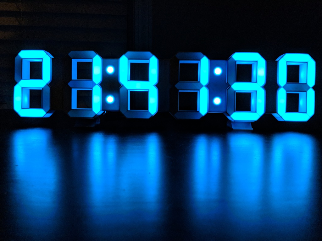
<p>Featured on <a href="https://all3dp.com/weekend-project-3d-print-a-sleek-7-segment-led-clock/">All3DP</a>!</p> <p>This <a href="https://en.wikipedia.org/wiki/Seven-segment_display">7 Segment</a> LED clock was designed to be almost entirely 3D printed, with the exception of a few fasteners... and of course, the electronic components, which are all neatly encased inside of the clock itself. It relies on the translucent properties of thin layers of white PLA to achieve the light diffusing necessary to light up individual segments. I created this project to get more experience in modelling for 3D printing using Fusion 360, practice my soldering skills, and get a chance to do a little ESP8266/Arduino programming.</p> <p>*<strong>Features</strong>*</p> <ul> <li>hang it from the wall using the built in hole(s) or print 2 optional stand pieces for a desktop configuration</li> <li>avoids clock drift by syncing with <a href="https://en.wikipedia.org/wiki/Network_Time_Protocol">NTP</a> periodically</li> <li>automatic time zone detection (uses IP to approximate your location, which should work for most scenarios; this can be overridden with a more accurate location if this is getting the wrong location)</li> <li>automatic daylight saving time adjustment - no need to spring forward or fall back manually</li> <li><a href="https://en.wikipedia.org/wiki/12-hour_clock">12-hour</a> or <a href="https://en.wikipedia.org/wiki/24-hour_clock">24-hour</a> format</li> <li>custom LED colors - over 16 million colors possible</li> <li>choose from hour:minute (HH:MM) or hour:minute:second (HH:MM:SS)</li> <li>over-the-air firmware updates</li> </ul> <h3>Print Settings</h3> <p><strong>Printer Brand:</strong></p> <p>Ultimaker</p> <p><strong>Printer:</strong></p> <p>Ultimaker 2</p> <p><strong>Rafts:</strong></p> <p>No</p> <p><strong>Supports:</strong></p> <p>No</p> <p><strong>Resolution:</strong></p> <p>0.15 mm layer height; 0.4 mm nozzle</p> <p><strong>Notes:</strong></p> <p>the colon cover pieces should be printed with at least 5 top and 5 bottom layers to ensure that the infill pattern cannot be seen</p> <h3>Post-Printing</h3> <p><strong>Supplies</strong></p> <p>Without considering the consumables and tools (wire, PLA, printer, soldering equipment, etc.), the supplies required for a clock come out to about $30. The list below contains links to the specific components that I purchased. Some of these items could take a while to arrive, so I would recommend ordering as early as possible.</p> <ul> <li><p>1x <a href="https://www.aliexpress.com/item/32529101036.html">WEMOS/LOLIN D1 Mini</a> (<a href="https://www.aliexpress.com/w/wholesale-wemos-d1-mini.html">clones work too</a>)</p> </li> <li><p>1x <a href="https://www.aliexpress.com/item/1m-4m-5m-WS2812B-Smart-led-pixel-strip-Black-White-PCB-30-60-144-leds-m/2036819167.html">WS2812B RGB LED strip (1m 60 LEDs/m IP30)</a></p> </li> <li><p>1x <a href="https://www.digikey.com/product-detail/en/cui-inc/PJ-037AH/CP-037AH-ND/1644547">PJ-037AH power barrel connector</a> (<a href="https://www.mouser.com/ProductDetail/490-PJ-037AH">Mouser alternative</a>)</p> </li> <li><p>1x <a href="https://oshpark.com/shared_projects/qbrdUYXd">clock shield PCB (with 2 oz copper, 0.8mm FR4 option)</a></p> </li> <li><p>1x <a href="https://www.digikey.com/product-detail/en/texas-instruments/SN74AHCT125N/296-4655-5-ND/375798">SN74AHCT125N 3V to 5V level shifting chip</a> (<a href="https://www.mouser.com/ProductDetail/595-SN74AHCT125N">Mouser alternative</a>)</p> </li> <li><p>4x <a href="https://www.homedepot.com/p/Everbilt-8-32-x-3-8-in-Coarse-Zinc-Plated-Steel-Round-Head-Combination-Machine-Screws-8-Pack-803081/204274610">nuts/screws (#8-32 x 3/8 in)</a> (6x for HH:MM:SS configuration)</p> </li> <li><p>1x <a href="https://www.aliexpress.com/item/1PCS-High-quality-5V4A-AC-100V-240V-Converter-Adapter-DC-5V-4A-4000mA-Power-Supply-US/32765050216.html">5V power supply (at least 3A recommended)</a></p> </li> <li><p>1x <a href="https://www.aliexpress.com/item/EClyxun-1pcs-5-5-2-1-mm-female-jack-to-5-5-2-1-mm-male/32834388615.html">Right Angle DC Power Connector Adapter</a> (only for desktop stand configuration)</p> </li> <li><p>wire (I used 3 colors of solid core 22AWG wire*)</p> </li> <li><p>Affiliate Link</p> </li> </ul> <p>NOTE: The diameter of the fastener holes are 4.5mm. If you must/want to use metric hardware, you could probably substitute the #8-32 x 3/8 in screws with M4 screws (6 to 9 mm length).</p> <p><strong>assembly animation</strong></p> <p><strong>Assembly</strong></p> <ol> <li>Upload the sketch and data files from <a href="https://github.com/leoclee/7-segment-clock">https://github.com/leoclee/7-segment-clock</a> to the D1 Mini (see detailed instructions on the github README). (Alternatively, you can check out a fork of the code that allows for a photoresistor by @RJFeddeler <a href="https://github.com/RJFeddeler/7-segment-clock">https://github.com/RJFeddeler/7-segment-clock</a>)</li> <li>Join the back pieces using the nuts and screws</li> <li>Solder the SN74AHCT125N level shifting chip to the clock shield PCB</li> <li>Solder the included 8 pin female headers from the D1 Mini to the clock shield PCB</li> <li>Solder the power and LED wires to the clock shield PCB</li> <li>Slide the clock shield PCB onto the pegs of back_hour_minute piece</li> <li>Solder the power barrel connector to the power wires (keep in mind the polarity of your power supply)</li> <li>Solder the LED wires to single LEDs in the colon positions of the back_hour_minute piece (keep in mind the direction of the LEDs, usually indicated by arrow(s) on the strip itself)</li> <li>Attach the D1 Mini to the PCB, sliding its male pins into the PCB's female header -- the circuit can be tested periodically from this point forward</li> <li>Continue soldering LEDs through the wire guides around the digits until all the LEDs have been soldered together in basically 2 strips, 1 going to the left of the controller (hours) and 1 going to the right of the controller (minutes and seconds)</li> <li>Cover all of the different segments or gaps with the appropriate 3D printed pieces</li> <li>(OPTIONAL) Attach stand pieces if not wall mounting</li> </ol> <p><strong>API Keys</strong></p> <ul> <li>For IP-based geolocation, you will require an <a href="https://ipstack.com">ipstack.com</a> API key. Their free tier allows for 10000 requests per month, which is way more than this clock will ever require. Note for <a href="https://pi-hole.net/">Pi-hole</a> users: ipstack.com and api.ipstack.com are blocked by default, so you will need to <a href="https://docs.pi-hole.net/core/pihole-command/#whitelisting-blacklisting-and-regex">whitelist</a> these domains.</li> <li>For determining UTC offset which takes into account DST rules, you will require a <a href="https://developers.google.com/maps/documentation/timezone/get-api-key">Time Zone API key</a> on Google Cloud Platform, where you get $200 credit per month to spend on usage for free. The clock's usage of the API will be so little, it should keep you well within this free tier.</li> <li>For runtime configuration of an override location, your Google Cloud Platform API key will also need to have the <a href="https://developers.google.com/maps/documentation/javascript">Maps JavaScript API</a> enabled.</li> </ul> Category: DIY
With this file you will be able to print 7 Segment LED Clock with your 3D printer. Click on the button and save the file on your computer to work, edit or customize your design. You can also find more 3D designs for printers on 7 Segment LED Clock.