Adafruit Feather Project Enclosure
thingiverse
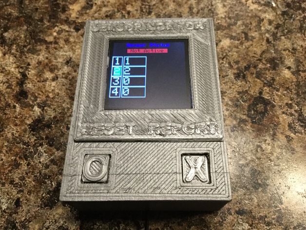
This is an enclosure for an Adafruit Feather that features an opening for a 1.44" Color TFT, Vibrating Mini Motor Disk, SPST Slide Switch, 3.7V LIION Battery (all from Adafruit), and two momentary contact switches with switch cover. The enclosure has a snap fit that holds the bottom in place. There is an opening for a USB to connect and charge the battery without opening the case. This is part of a larger project still in progress. This is being shared for others who may be looking for an enclosure for similar components. The Feather used for this project is the Feather 32u4 with RFM69HCW Radio Module. This unit is used to monitor the status of several sensors using the RFM69HCW radio. As always, I have included the 123D Design files so this can be modified to your needs. Information for this project can be found here: http://www.instructables.com/id/Sensor-Array-and-Monitor/ Print Settings: Printer Brand: Printrbot Printer: Simple Black Rafts: No Supports: Doesn't Matter Resolution: 2.6 mm Infill: 30% Post-Printing: As you can see by the instructions below, this is a rather complicated build. The instructions are general, so you will need to test fit and plan ahead. Wire routing is important so make sure you figure this out before getting too far. Once the parts are glued together, it will be difficult to make wiring changes. It is suggested to open the 123D file and you can see all the parts assembled. Viewing the assembled project in 3D may help when reading the instructions below. Some parts need to be glued together after wiring is installed. I used the 30 AWG Si wire from Adafruit. It's small and very flexible. I didn't use the header pins on the Feather or TFT display to make the enclosure as small as possible. Some of the parts may need some minor filing or drilled to fit properly. Test fit everything and trim so all parts fit. I have updated the 123D files with modifications I made and are included in the downloads. First: Solder wires to the required pins on the bottom of the Feather. The wires need to be soldered to run centered from the pin holes so they match up with the holes on the inner board. Leave the wires long. They can be trimmed after the feather is put in place. Pass the wires from the Feather through the corresponding holes in the inner board, then route them back through the slot, or hole for soldering to the associated component. Step 2: Glue the two dimples on the sides of the inner board into the two holes in the top cover. This is a good time to test everything. Step 3: Test fit the bottom and file if needed to fit tightly. Glue the bottom to the inner board only. The enclosure can still be opened by pulling on the bottom when the glue is cured. You can also use a small screwdriver in the side holes to help open the case. Step 4: Glue the screen cover in place. Make sure the viewable part of the TFT is visible through the window. Glue only on the top cover and screen cover. Be careful not to get glue on the TFT display. Note: use little, or no glue on the top edge! There is only a narrow edge for glue on the top. Step 5: Solder the wires from the bottom and align them directly centered in the holes. Route the wires through the holes in the inner board. Route the wires from the Feather to the slot or other holes depending on the final connection. Note, the battery will share this space, so keep the wiring as flat as possible. How I Designed This: I modeled all the components not printed. These are all included in the 123D files. I arranged the components in 3D to allow for a compact size. The outer enclosure and inner supports were designed around the components. During the build, when I had to make modifications without re-printing, I modified the 123D files with the change.
With this file you will be able to print Adafruit Feather Project Enclosure with your 3D printer. Click on the button and save the file on your computer to work, edit or customize your design. You can also find more 3D designs for printers on Adafruit Feather Project Enclosure.