ADAMnet Drive Emulator Case
thingiverse
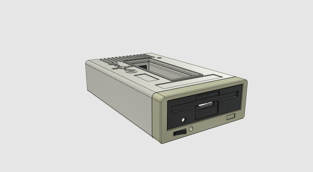
It appears that the text is a step-by-step guide on how to assemble a custom case for an Atari ADAM computer using 3D printing. The author provides detailed instructions, including pictures, on how to build and assemble the case, as well as tips and advice on how to troubleshoot common issues. Here are some key points from the text: 1. **Assembly**: The guide takes you through the process of assembling the case, starting with preparing the components, such as the LCD module, Arduino PCB, and RJ11 connector. 2. **Case design**: The author mentions that they used a combination of 3D printing and laser cutting to create the case, which includes a top shell, main case, and base. 3. **Components**: The guide lists the required components, including an LCD module, Arduino PCB, RJ11 connector, and microSD board. 4. **Troubleshooting tips**: The author provides advice on how to troubleshoot common issues, such as dealing with messy wiring, finding the right contrast setting for the LCD module, and avoiding damage to precious retro hardware. 5. **Additional resources**: The text includes links to online forums where the author has shared additional information and guidance. The guide is intended for individuals who have already built the ADAM computer using the Arduino-based kit provided by Sean Myers. It's a detailed and step-by-step guide, but it assumes some level of technical knowledge and experience with 3D printing and electronics. Some possible questions or areas for discussion related to this text could be: * How did you find the process of assembling the case? Was it challenging or frustrating at any point? * Have you encountered any issues with the wiring or electronics that are not addressed in the guide? * Do you have any suggestions for improving the design or assembly process of the case? * Are there any additional resources or online forums that you would recommend for people interested in building and customizing retro computers?
With this file you will be able to print ADAMnet Drive Emulator Case with your 3D printer. Click on the button and save the file on your computer to work, edit or customize your design. You can also find more 3D designs for printers on ADAMnet Drive Emulator Case.