ADAMnet Drive Emulator Mount
thingiverse
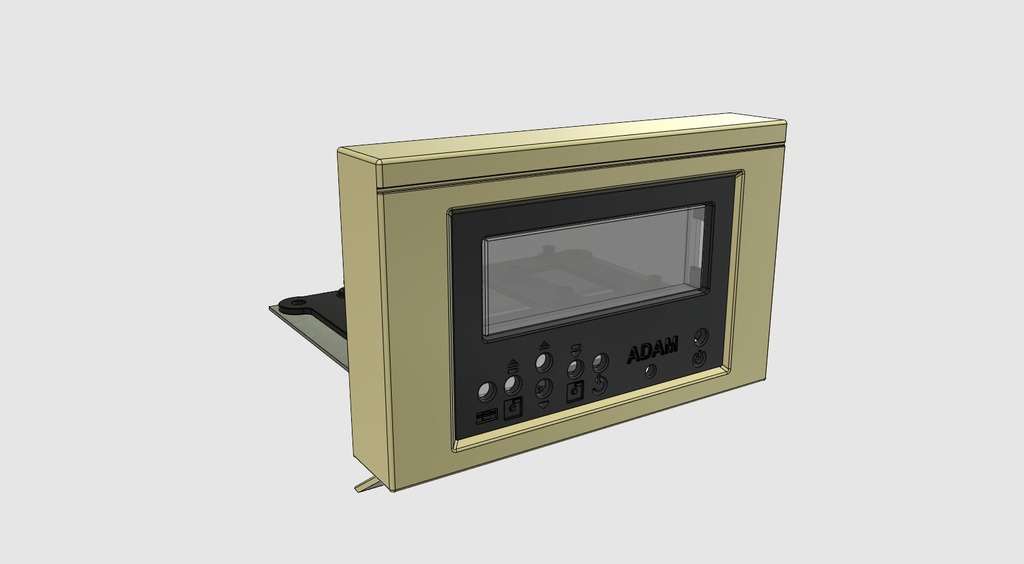
ADAMnet Drive Emulator Mount A little while back I posted a design for a 3D printed case for the awesome ADAMnet floppy drive emulator for the Coleco ADAM, designed to look like an ADAM floppy drive. More info here: https://github.com/Kalidomra/AdamNet-Drive-Emulator There is now a commercial version by the same author - find him on facebook if you must go there. I thought I'd do another solution for the DIY'er who may not want a further external box, even if it is a cute little floppy drive, awwww! As ADAM owners know the computer supports two digital data drives but most have a blanking plate in place of the right-hand one. This solution is nice and easy, convenient, uses that blanking plate, and the mod is fully reversible. The Highlights: -Print out the face_plate.stl as oriented, with support. -Carefully remove the locking tabs holding the metal bracket to the blanking plate -Remove said metal bracket and the perspex window -Insert the display module in to face_plate.stl - it should just snap in -Push the whole lot home in place of the perspex window - it should snap in to place -Replace the metal bracket and locking tabs -Print arduino_support.stl and clip your modded Arduino Mega to that -Take some double-ended female patch wires and connect the two devices (sorry you can't plug the display and Arduino directly together, not enough room) -Fit the whole lot back in to your ADAM, the blanking plate's screws will also serve to hold down arduino_support.stl -Done! Ok, ok, the Devil is in the detail: Apart from modding your Arduino Mega as per the ADAMnet github page there are some other considerations: -Power -Communication -On/Off switch -Access to the buttons on the display module -Power / Activity LED Power: Power can be easily obtained from the spare data drive headers located just behind the blanking plate. See Data_Drive_Headers.txt for more info. I'd go for a GND and +12v(L) as the Arduino can take it and even if you haven't upgraded your ADAM's PSU there should be more than enough juice. Communication: Having followed the github build instructions you will be wondering where to route the ADAMnet communications lines - there is no internal header. The easy solution would be to cut one end off an ADAMnet cable (six way telephone cable basically) and feed the cut end of the cable in to the ADAM past the ADAMnet port on the left side of the machine. With a bit of jiggling you should be able to feed the cut end to a convenient hole near the ADAMnet emulator and fish it out - connect as per github instructions, having some kind of socket here would be a good idea. Once wired up the other end of the cable can be plugged back in to the ADAMnet port on the side of the machine. Pros: -Reasonably easy -You have an easy option to unplug the drive Cons: -Not so neat -Multimeter required to check the wiring Another option if to disassemble your ADAM and solder the wires directly to the PCB where one of the ADAMnet ports attaches, probably the keyboard one - as ADAMnet is a serial protocol this shouldn't be an issue. Pros: -Ultimately neater -More reliable in the long term Cons: -More effort required -Much higher chance of FUBARing your ADAM On/Off Switch: I've included a space for a 7mm latching push on/off switch in the front panel, the latching bit is important and I'd strongly suggest getting one with at least 6 pins (three separate lines) as I'd recommend running the comms lines as well as the power line through it - why? Well I've noticed the ADAM can get a bit funky if finds a device on the end of an ADAMnet line but said device isn't switched on. A bit of a problem if you want the machine powered without the ADAMnet emulator. Display module buttons: You'll notice they don't poke out of the front panel. Not being able to control the device could be considered to be something of an issue! The two solutions I'd suggest are: 1) Desolder the current tact switches and replace with longer ones - 6x6x12mm shroud do. Pro's: -Nice, robust solution Con's: -More fiddly soldering 2) Buy some little buttons to fit the holes to make up the gap. Pro's: -Pretty buttons -Lower chance of breaking something Con's: -Putting it all together will be an exercise in frustration -...and again any time you want / need to take it apart -There's lots of choice on the likes of fleaBay but you'd be surprised how hard it is to get the measurements right. Power / Activity LED: The final hole is to allow a 3mm LED. This can be wired for Power, Activity, or both if you go for a multi-input (probably RGB) LED. Powering the LED is easy, look for a spare power and GND on the arduino and fill your boots - do be sure to include a suitable resistor in series depending on the specs of your LED and the voltage rail you are using! An activity LED is trickier. The most sensible way to wire that up is to look at the activity_wiring diagram for inspiration, assuming the (micro)SD shield you are using is suitable. You might also try removing the tiny SMD activity LED from the Arduino and running wires from the free pads to a LOW POWER LED on the front panel. Bonus Points: As the decals on the front panel are indented you could fill them with a contrasting colour to help make them stand out. The mock-up ADAM parts (shell and bracket) are reasonably accurate so you may also find those useful for printing replacement parts. The Display shield mock-up is also reasonably accurate so could prove generally useful.
With this file you will be able to print ADAMnet Drive Emulator Mount with your 3D printer. Click on the button and save the file on your computer to work, edit or customize your design. You can also find more 3D designs for printers on ADAMnet Drive Emulator Mount.