Adjustable height E3D V6 nozzle seat for dual nozzle 3D printers
prusaprinters
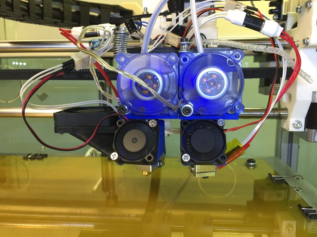
<p>Adjusting the nozzle height on some dual nozzle printer rely solely on the accuracy of the components. One such printer is the German RepRap X400. There is no easy way of setting both nozzle's height correctly.</p> <p>This nozzle seat solves this problem with a linear cam height adjustment mechanism embedded inside the nozzle's clamp. This clamp aligns the nozzle with the MK8 hobbed gear. Together with the push lever, this is a revised extruder for the X400, but will work with most direct drive extruders. It provides a height adjustment of about 2.40mm.</p> <p>UPDATE:<br/> More elegant design without the screw cap. Now the screw is fully contained in the block. Tightening screw for the nozzle added to fully secure it in place.</p> <p>UPDATE 2:<br/> Use the vernier patterns to calculate the nozzle offsets down to 0.1mm.</p> <h3>Print instructions</h3><p>Unassociated tags: adjustable height, fan duct, tightening screw</p> <h3>Category: 3D Printer Parts Summary</h3> <p>Adjusting the nozzle height on some dual nozzle printer rely solely on the accuracy of the components. One such printer is the German RepRap X400. There is no easy way of setting both nozzle's height correctly.</p> <p>This nozzle seat solves this problem with a linear cam height adjustment mechanism embedded inside the nozzle's clamp. This clamp aligns the nozzle with the MK8 hobbed gear. Together with the push lever, this is a revised extruder for the X400, but will work with most direct drive extruders. It provides a height adjustment of about 2.40mm.</p> <p>UPDATE:<br/> More elegant design without the screw cap. Now the screw is fully contained in the block. Tightening screw for the nozzle added to fully secure it in place.</p> <p>UPDATE 2:<br/> Use the vernier patterns to calculate the nozzle offsets down to 0.1mm.</p> <h3> Post-Printing</h3> <p><strong>BOM and Instructions</strong></p> <p>Push Lever:<br/> Print on the top surface (0.2mm layer is fine)<br/> 1x M4x12 socket head screw<br/> 1x 25mm spacer (OD 4.76mm, ID 3.6mm)<br/> 1x 13x4x5 ball-bearing<br/> 1x M3x30 socket screw<br/> 1x M3 washer<br/> 2x M3 oversized washers<br/> 1x M3x60 socket head screw<br/> 1x M3 nut<br/> 1x 10 turn spring (OD 10mm, uncompressed length 30mm) or shorter stiffer spring</p> <p>Adjustable height clamp:<br/> Print these parts with 0.1mm layer height for accuracy. No supports needed. A brim of 10 lines will help adhesion and prevent ABS from warping.<br/> Print the halves on their sides, with the cavities upward.<br/> Print the key on its ramp, the square slot pointing up.<br/> Print the lift ramp flat on the spring hole surface.<br/> Print the screw cap on its front flat.<br/> 1x M3x20 socket head screw<br/> 1x M3x15 socket head screw<br/> 2x M3 square nut<br/> 4x M2x10 socket head screws<br/> 1x print bed spring (OD 4.8mm, L 7mm)<br/> 2x M3x30 socket head screws<br/> 2x M3 washers<br/> 1x paperclip</p> <p>Clean up the printed parts and file the mating surfaces, mainly the key and the lift ramp surfaces. Ream all holes to their sizes with drill bits, except for the 4 2mm holes in the front half of the clamp, these will be self-tapped by the M2 screws when closing the screw cap.<br/> Press the square nut in the middle of the key in the slot provided. Careful not to break the key, not much tolerance there.<br/> Assemble the front part of the clamp by capturing the head of the M3 socket head screw (adjustment screw), threads towards the inside, with the screw cap and the 4 M2 screws. You'll have to self-tap the screws in. This is my solution in the absence of a proper retaining ring screw!<br/> Thread the key on the adjustment screw all the way in, with the square nut facing the bottom of the clamp (ramp facing up the cavity).<br/> Place the E3D heat sink in the clamp along with the lift ramp, with the ramp pointing downwards.<br/> Place the spring in the cavity provided with a little compression.<br/> Close the other half, making sure that the spring is contained.<br/> Attach the nozzle and heating block as per E3D instructions.<br/> Bolt the assembly to the NEMA17 motor using the two M3x30 bolts, don't tighten fully yet.<br/> Using an Allen key, adjust the height of the nozzle. A counter clockwise turn will push the key under the ramp, thus raising the height of the nozzle. A clockwise turn will pull the key, and lower the nozzle, thanks to the spring. Once the nozzle's height is set, tighten the bolts.</p> <p>UPDATE:<br/> The height adjustment screw is now retained with a paperclip passed through the provided holes.<br/> Tightening screw with captive square nut pushes the piston against the heat sink's collar.</p> <p>Make adjustments with the tightening screw loose, then tighten gently just enough to keep the heat sink rotating and wobbling.</p> <p>Enjoy!</p>
With this file you will be able to print Adjustable height E3D V6 nozzle seat for dual nozzle 3D printers with your 3D printer. Click on the button and save the file on your computer to work, edit or customize your design. You can also find more 3D designs for printers on Adjustable height E3D V6 nozzle seat for dual nozzle 3D printers.