Adjustable Router Template Coupler
thingiverse
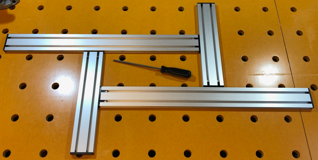
This is my solution to the Festool MFS-400 or Woodpeckers Variable Router Jig adjustable router templates. It uses a narrower version of the same extruded aluminum profile used by Woodpeckers. I have no idea if it will be available where you are, I'm in Japan and have linked to my supplier to assist in identifying the items, or as a last ditch source of getting the parts in your area. Total cost to me was about $50 US, quite a savings over the commercial solutions. Required Parts: * Aluminum Profile: Alfa Frame System AFS-1560-6 (4 pieces are required, I used 2 x 300mm long and 2 x 600mm long sections, pre-cut from the supplier.) * PETG filament. I tested with Carbon Fiber infused PLA and there was not adequate flexibility or friction from the parts for this to work. PETG is finicky, it must be totally dry and needs a well tuned profile. I use Chinese made Sunlu PETG+ on an Ender 3 with Maker's Muse PETG profile. * M6 X 25mm narrow head (8.4mm head diameter with smooth sides) cap screws (8 required) You have to use a similar screw, normal M6 cap screws will not work! I have uploaded an alternate version that is designed for standard M5 x 25mm cap head allen screws, but the profile is designed to align using M6, so I can't promise it will work as well or at all with M5 screws. The Woodpeckers design machines a slot through the profile and transfers the force of the screw using a steel plate, which is obviously a much more robust solution. I just don't like the idea of machining big grooves in this lovely extrusion, and most people don't have access to a milling machine. My solution seems more than strong enough so far, is quite square, eliminates metal on metal contact between the extrusions and the profile is otherwise unmolested and can be used for other jigs and solutions. The 6.5 degree angle of the screw, slightly compliant nature of the PETG, and tight tolerance press fit of the insert itself seems to be enough to retain it strongly. (If you are having issues I have an alternate design that uses grub screws to reinforce this junction but would require drilling/tapping the profile.) Both commercial designs have built in scales/rulers on their extrusions, but I use my digital calipers or a seperate rule to get accurate dimensions. I'm pretty sure that Woodpeckers just directly laser engraves the anodized layer of these extrusions, so you may want to give that a try at your local makerspace if it is important to you. 1. Print 4 of the Rail_Insert and 4 of the Backing_Plate parts. You can optionally print 4 of the End_Cap parts to create a clean look and cover the sharp edges. 1. Gently tap the parts into the end of the profile to remove any frayed extrusion. Make sure it seats well. I found bracing the face of the printed part on a flat surface and tapping the end of the rail onto it is the best way to ensure even pressure and successful insertion. 1. Insert the Backing_Plate with the arrow pointing up into the edge slot of the profile, and gently mate the two profiles together in an "L" shape. Make sure the arrow is pointing up so that you are matching the angle of the bores. Alternately tighten the bolts into the Backing_Plate, tightening them to a slip fit. 1. Repeat with the other two profiles, but make sure they are in a complimentary configuration as shown. With the two "L" parts adjusted to the same distance insert the remaining two Backing_Plates and carefully join the two "L" shaped pairs together. It is important to tighten the connections in pairs (both long sections, then both short sections for example) to ensure they stay square and you don't put unnecessary stress on the joints. If you tighten them in a circular order it is much more likely you will be out of square and create strain on the parts. It is CRITICAL that you use this with a proper router guide bushing (or appropriate top bearing bit) in place or you will have a really bad day. If you need help calculating the dimensions you need to set on the template in order to achieve your desired opening, I suggest starting with this helpful website.
With this file you will be able to print Adjustable Router Template Coupler with your 3D printer. Click on the button and save the file on your computer to work, edit or customize your design. You can also find more 3D designs for printers on Adjustable Router Template Coupler.