AI3M S Optical Endstop Z-Level
thingiverse
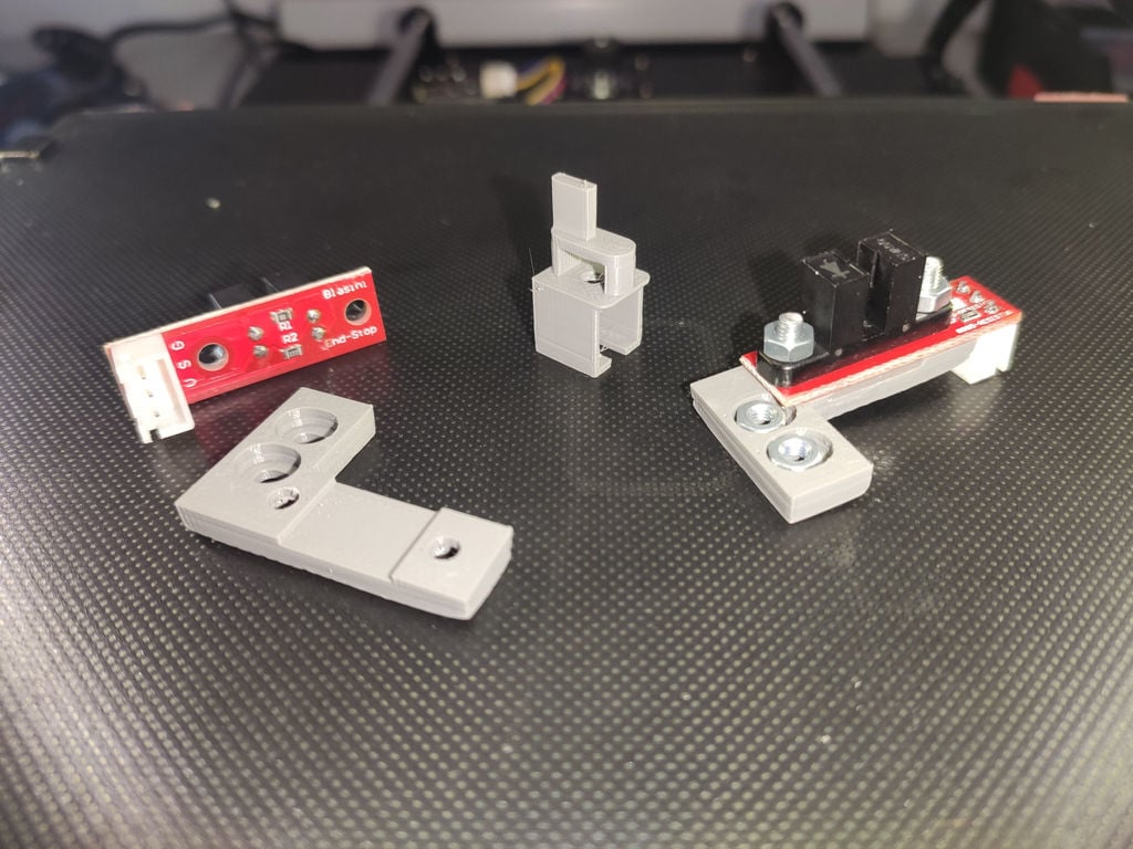
<b>-english translation below-</b> AI3M-S (Anycubic I3 Mega S) Umbau auf Optische (Z-)Endschalter Was braucht man für diesen Umbau: <ol> <li> Optische Endstops, wie ihr sie auf Amazon, Ali und sonstwo findet (5V) (Ich hatte diese hier: https://www.amazon.de/dp/B01B4FV0HQ/ref=cm_sw_em_r_mt_dp_LA8TFbCBDE450 ) </li> <li>Jeweils ein weiteres Kabel als Spannungsversorgung für die Endstops (Board -> Endstop).. (falls kein Kabel bei den Enstops dabei ist)</li> <li>Eine Firmware zum selber compilieren (ich nutzte diese hier: https://github.com/davidramiro/Marlin-Ai3M-2.0.x )</li> <li>Die Arduino IDE ( https://www.arduino.cc/en/main/software )</li> <li>und ein paar gedruckte Endstophalter/Adapter und Unterbrecher (keine Ahnung wie man das nennt ^^ ) für die Levelschrauben</li> <li>Lötkolben oder 1-2 Jumper Pins (2,54mm)</li> </ol> Und ein bisschen Bastel-Affinität, Seitenschneider, ein paar M3 Schrauben+Muttern, ganz kleinen Schlitz-Schraubendreher oder Spitze Pinzette (um die Belegung des JST-Steckers zu ändern) Wo bekomme ich die 5V her, um die Endstops mit Spannung zu versorgen? Ich hab gemessen und ansich ist es egal, alle 5V Pins, haben das selbe Potential. Anbieten würden sich die 5V Pins von: D42 und D43 oder einer Endschalter (V) Da die bisherigen Endschalter die 5V von der Huckepackplatine bekommen und die zu schwach ist, kann man die leider nicht übernehmen. Aber dafür passt der Rest ^^ Also einen der 5V-Pins über einen Jumper-Pin (oder kurzerhand festlöten) per Kabel zu den Endschaltern bringen. Dann die Steckerbelegung an den Endschalter entsprechend der Bezeichnungen neu Belegen (G->G, S->S, 5V->V). Ansich kann man das Ganze jetzt auch schon testen: Mit dem G-Code "M119" könnt ihr die Zustände der Endstops abfragen. Aber Bitte keine Home-Fahrt machen!! <b>--> Vorsichtshalber eine Hand am Netz-Schalter!!!!!</b> Dann die Endstops auf dem gedrucktem Adapter befestigen (2x M3 Schraube+Mutter) und diesen am Rahmen anbringen (Entweder Schrauben+Muttern, oder ein Gewinde in den Adapter schneiden) Danach noch den "Unterbrecher" an der Stellschraube für das Leveln befestigen und grob Einstellen (Ausgeschaltete Motoren, Z-Achse per Hand verfahren/drehen -> Bitte beide Seiten gleichzeitig ^^ ) Wenn nun Mechanisch/Elektrisch alles passt, geht es an die Firmware. Ihr bearbeitet/startet/Öffnet die "Marlin.ino" aus eurer heruntergeladenen und entpackten Firmware. Wählt unter Tools -> Board: "xxx", das "Arduino Mega or Mega 2560" aus. Öffnet nochmal die "Marlin.ino" falls noch nicht geschehen und ändert die Parameter, die ich euch unten Aufgelistet habe. (In der DavidRamiro Firmware, müsst ihr zusätzlich die Stepper-Treiber anpassen! und wie ich gemerkt hatte auch die Drehrichtung umkehren) Firmware Änderungen: Stepper-Treiber Anpassungen (Stock Driver -> A4988) <pre><code> ////// Endstop Settings // Mechanical endstop with COM to ground and NC to Signal uses "false" here (most common setup). #define X_MIN_ENDSTOP_INVERTING true // set to true to invert the logic of the endstop. #define Y_MIN_ENDSTOP_INVERTING true // set to true to invert the logic of the endstop. #define Z_MIN_ENDSTOP_INVERTING false // set to true to invert the logic of the endstop. #define X_MAX_ENDSTOP_INVERTING false // set to true to invert the logic of the endstop. #define Y_MAX_ENDSTOP_INVERTING true // set to true to invert the logic of the endstop. #define Z_MAX_ENDSTOP_INVERTING true // set to true to invert the logic of the endstop. #define Z_MIN_PROBE_ENDSTOP_INVERTING false // set to true to invert the logic of the probe. /** * Stepper Drivers */ #define X_DRIVER_TYPE A4988 #define Y_DRIVER_TYPE A4988 #define Z_DRIVER_TYPE A4988 #define X2_DRIVER_TYPE A4988 #define Y2_DRIVER_TYPE A4988 #define Z2_DRIVER_TYPE A4988 #define Z3_DRIVER_TYPE A4988 #define Z4_DRIVER_TYPE A4988 #define E0_DRIVER_TYPE A4988 #define E1_DRIVER_TYPE A4988 #define E2_DRIVER_TYPE A4988 #define E3_DRIVER_TYPE A4988 #define E4_DRIVER_TYPE A4988 /** * Default Axis Steps Per Unit (steps/mm) */ #define DEFAULT_AXIS_STEPS_PER_UNIT { 80, 80, 400, 384 } // @section machine // Invert the stepper direction. Change (or reverse the motor connector) if an axis goes the wrong way. #define INVERT_X_DIR true // set to true for stock drivers or TMC2208 with reversed connectors #define INVERT_Y_DIR false // set to false for stock drivers or TMC2208 with reversed connectors #define INVERT_Z_DIR false // set to false for stock drivers or TMC2208 with reversed connectors // @section extruder // For direct drive extruder v9 set to true, for geared extruder set to false. #define INVERT_E0_DIR false // set to false for stock drivers or TMC2208 with reversed connectors #define INVERT_E1_DIR false // set to false for stock drivers or TMC2208 with reversed connectors </code></pre> Wenn Ihr die Änderungen eingetragen habt, müstt ihr das ganze compilieren: "Sketch" und "Export compiled binary" Dann die "Marlin.ino.hex" aus dem Marlin Verzeichniss auf den Drucker Überspielen. Falls ihr es benötigt, für z.B. "Firmware Updater" über Octoprint: Flash method: avrdude AVR MCU: ATmega2560 AVR Programmer Type: wiring Nach Erfolgreichen Flashen, müsst ihr noch mit "M502" die Standard Werte laden und mit "M500" speichern. Extruder kalibrieren, PID-Tuning durchführen, Bett Leveln, glücklich sein :-D Ich hoffe ich habe nichts vergessen und es hilft euch für euren Umbau weiter! ################################################################ Conversion to optical (Z) limit switches What do you need for this conversion: Optical end stops, as you can find them on Amazon, Ali and elsewhere (5V) (I had these here: https://www.amazon.de/dp/B01B4FV0HQ/ref=cm_sw_em_r_mt_dp_LA8TFbCBDE450) Another cable each as a power supply for the end stops (board -> end stop) .. (if no cable is included with the end stops) A firmware to compile yourself (I used this here: https://github.com/davidramiro/Marlin-Ai3M-2.0.x) The Arduino IDE (https://www.arduino.cc/en/main/software) and a couple of printed end stop holders / adapters and breakers (no idea what they are called ^^) for the level screws Soldering iron or 1-2 jumper pins (2.54mm) And a bit of craft affinity, wire cutters, a few M3 screws + nuts, very small slotted screwdrivers or pointed tweezers (to change the assignment of the JST connector) Where do I get the 5V to supply the end stops with voltage? I measured it and it doesn't really matter, all 5V pins have the same potential. The 5V pins of: D42 and D43 or a limit switch (V) would be suitable Since the previous limit switches get the 5V from the piggyback circuit board and it is too weak, it unfortunately cannot be used. But the rest fits So bring one of the 5V pins to the limit switches via a jumper pin (or simply solder it on) by cable. Then reassign the pin assignment at the limit switch according to the designations (G-> G, S-> S, 5V-> V). Actually, you can already test the whole thing: With the G-Code "M119" you can query the status of the end stops. But please do not drive home !! <b>-> As a precaution, put one hand on the power switch !!!!!</b> Then fix the end stops on the printed adapter (2x M3 screw + nut) and attach it to the frame (either screws + nuts, or cut a thread in the adapter) Then attach the "interrupter" to the adjusting screw for leveling and roughly adjust (switched off motors, Z-axis move / turn by hand -> please both sides at the same time ^^) If everything fits mechanically / electrically, it goes to the firmware. You edit / start / open the "Marlin.ino" from your downloaded and unzipped firmware. Select under Tools -> Board: "xxx", the "Arduino Mega or Mega 2560". Open the "Marlin.ino" again if you haven't already done so and change the parameters that I have listed below. (In the DavidRamiro firmware, you also have to adjust the stepper drivers! And as I noticed, also reverse the direction of rotation) Firmware changes: Stepper driver adjustments (Stock Driver -> A4988) When you have entered the changes, you have to compile the whole thing: "Sketch" and "Export compiled binary" Then transfer the "Marlin.ino.hex" from the Marlin directory to the printer. If you need it, e.g. for "Firmware Updater" via Octoprint: Flash method: avrdude AVR MCU: ATmega2560 AVR Programmer Type: wiring After successful flashing, you still have to load the standard values with "M502" and save with "M500". Calibrate extruder, perform PID tuning, bed leveling, be happy :-D I hope I haven't forgotten anything and it will help you with your renovation!
With this file you will be able to print AI3M S Optical Endstop Z-Level with your 3D printer. Click on the button and save the file on your computer to work, edit or customize your design. You can also find more 3D designs for printers on AI3M S Optical Endstop Z-Level.