Air Quality & Aerosol (CO2, TVOC) Sensor and Alarm (COVID)
thingiverse
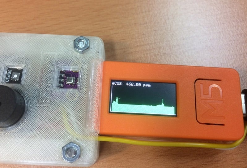
# Air Quality & Aerosol (VOC) Sensor and Alarm Please download the controller code from my GitHub: https://github.com/Spo-ck/Air-Quality-Aerosol-VOC-Sensor-and-Alarm During the COVID-19 Pandemic, monitoring the Air Quality is important. Because of this, I developed this compact Air Quality Monitor based on the M5StickC Microcontroller and the SGP30 Sensor. The System is very small and can also be worn as a smart watch. When the eCO2 hits the threshold of 1000 ppm or the TVOC hit the threshold of 150 ppb, the sensor will trigger an alarm (sound and lght), so that you can leave a dangerous and potentially infectious room or open the windows.  ***System Chart View***  ***System Chart View*** ## Electronic ### Part List #### Electronic * [Buzzer module](https://www.makershop.de/module/audio/passiver-buzzer-summer/) * [BME280 Barometric Sensor](https://www.makershop.de/sensoren/temperatur/bme280/) * [GY-SGP30 Gas Sensor (alternative Grove SGP30)](https://www.ebay.de/itm/GY-SGP30-Air-Quality-Sensor-Breakout-VOC-and-eCO2-QITA/353147995118?hash=item523942c3ee:g:GLcAAOSwIZ9fGU-k) * [M5StickC Microcontroller](https://eckstein-shop.de/M5Stack-M5StickC-PLUS-ESP32-PICO-Mini-IoT-Development-Kit) * [Grove Sensor Cable](https://eckstein-shop.de/M5Stack-Buckled-Grove-Cable-20cm-5pcs) * [PCB](https://www.reichelt.de/punkt-streifenrasterplati-hartpapier-160x100mm-h25ps160-p23953.html?&trstct=pol_5&nbc=1) * [Generic 1x8 Pin Header 2,54mm](https://www.conrad.de/de/p/wws-40-g-sl40g1-pin-header-1x40-rm2-54-straight-au-inhalt-20-stueck-800166396.html) * Generic solid core wires (PCB) * Generic Lead Solder #### Tools * [Soldering Station](https://www.conrad.de/de/p/basetech-zd-931-loetstation-digital-48-w-150-bis-450-c-1460697.html) * [Solder Pump](https://www.conrad.de/de/p/toolcraft-lee-192-entloetsaugpumpe-antistatisch-2196503.html) * [Third Hand](https://www.conrad.de/de/p/inline-dritte-hand-mit-lupe-800404647.html) * [Soldering Tools](https://www.conrad.de/de/p/toolcraft-lns-151-platinenbesteck-6teilig-2182257.html) ### Pin Mapping * GND: Buzzer Module -, BME280 GND, SGP30 GND * 3.3V: Buzzer Module +, BME280 VIN, SGP30 VIN * G26: Buzzer Module S * G32: BME280 SDA, SGP30 SDA * G33: BME280 SCL, SGP30 SCL  ***Electronic Schematic*** ### Assembly The system basically consists out of the M5StickC Microcontroller, a Buzzer Module, a BME280 Barometric Sensor Module (Temperature, Humidity, Pressure) and an SGP30 Gas Sensor Module (eCO2, TVOC, Ethanol, H2). The Buzzer Module is connected to the M5StickCs Pin Header, and the seonsors are connected to the I2C bus via the Grove connector. All 3 components are soldered together on a single prototyping PCB. To this prototyping PCB is then soldered a 1x8 Pin Header (2.54mm) so that the PCB can be connected to the front pin header of the M5StickC. As power supply off all 3 modules, the 3.3V and the GND Pin of the M5StickCs Pin Header are utilized. The Buzzer-Modules signal pin is soldered to Pin 26, because this pin allows output signals. Because of the sensor modules need to be connected to the I2C Bus, which is only available on the Grove connector of the M5StickC, a 20cm Grove sensor cable was utilized. One connector was cutted of, and the 5V and GND Cables were removed. The remaining Yeallow (G32, SDA) and white (G33, SCL) cables were soldered to the corresponding pins on the PCD, to connect them to the sensor module  ***PCB Front***  ***PCB Back***  ***PCB Cased*** ## 3D-Printing ### Settings * Profile: 0.2mm * Infill: 10% * Support: Yes ### Parts * Filament: PLA ([OWL-Filament](https://owl-filament.de)) * Printer: Creality Ender 3 * Generic M3 Screws ### Assembly The Sensor PCB Case consists out of 3 parts, a body frame, a front and a bottom part. For the Assembly, the Soldered PCB is first fittet into the Body Frame from the bottom so that the case mathes the pin header exactly. The Sensor cable is the placed into the small hole on the top side of the frame. After that, the Front and Bottom Party are crewed to the case. The Screwd sensor case it then first plugged into the Pin Header of the M5StickC. After that, the Sensor Cable is plugged into the Grove Connecter.  ***PCB Cased***  ***System Detailed View*** ## Arduino Code [You can download the code from my Github](https://github.com/Spo-ck/Air-Quality-Aerosol-VOC-Sensor-and-Alarm) ### Libraries * [M5StickC](https://github.com/m5stack/M5StickC) * Wire.h * [Adafruit_Sensor.h](https://github.com/adafruit/Adafruit_Sensor) * [Adafruit_SGP30.h](https://github.com/adafruit/Adafruit_SGP30) * [Adafruit_BME280.h](https://github.com/adafruit/Adafruit_BME280_Library) * EEPROM.h ### About the Code  The purpose of this Microcontroller Code is to generate sensor data from the sensors connected to trigger an Alarm when the Air Quality is bad. For this reason, the SGP30 Sensor Module measures eCO2 and TVOC in the breathing Air. The BME280 Barometric Sensor is required to calibrate the SGP30, and therefore to enhance its accuracy. When the eCO2 value is over 1000 ppm, or the TVOC value is over 150 ppb, an alarm is triggered. The alarm will result in an alarm sound provided by the buzzer modele, the built in LED enlight in RED and the display turning RED. By the built in settings options, the Buzzer can also set into silent mode, where only the LED and the Display are tiggered in case of an alarm. The alarm sound is only triggered once in 60s, when the eCO2 or TVOC value hits the threshold value, but the LED will be enlighted in RED untill the Sensor Value is below the threshold again. In addition, the buzzer then disabled for 1 minute. Because of this, you will not hear multible buzzer alarms, when the sensor value is falling below, and hitting the threshold again within one minute.  ***System Alarm*** The System has three built in views. The Detailed View shows only the eCO2 and the TVOC values, whereas the Air Quality view shows the Time, Temperature, Humidity and the Battery Status in addition. More advanced is the Chart View, which shows the eCO2 value for the last 20min. If the critical threshold was hit, the bar shown will turn red, and if the value is below, the bar will be green. To navigate through the different views, the front button (Button A) is used. The last view is also stored in EEPROM, so that the sensor will start in the last used view when it starts next time.  ***System Detailed View***  ***System Air Quality View***  ***System Chart View***  ***System as Smart Watch close up*** Nomally, the display is On all time, but it is also possible to disable the display. In this mode, the front button needs to be pressed one time to turn the display on for 5s. After that, pressing this button again will make the view change as usual. In addidion, a settings view is implemented. In the settings view, one can change the Display Mode (Display always on or on for 5s) and the Alarm Mode (Buzzer turned off or on). This view is opened when the side button (Button B) is pressed. In this view, the first option it the Display Mode. When the Front Button is pressed, the Mode will change (Display always on or on for 5s). The option is confirmed with pressind the side button again. After that, the settings for the Alarm Mode (Buzzer turned off or on) is opened and can be changed with pressing the front button. In general, the active settings option is indicated with a red line on the left side. Pressing the side button a third time will confirm the settings, and open the last Sensor View again.  ***System Settings*** ### How To In order to flash this code on the M5StickC, the Arduino IDE needs to download and to be installed first. Then, the M5StickCs driver and the above mentioned libraries need to be installed. You can then open (or copy/past) the code into the IDE and flash it. * [M5StickC Manual and Software](https://m5stack.com/pages/download) * [Arduino IDE](https://www.arduino.cc/en/software) ## Limit Values In my design I used the value of 1000 ppm eCO2 and 150 ppb TVOC as limits for an alarm of the Sensor System. These limits mark the boundary condition for unobjectionable indoorair, above the limits the airquality is questionable, but not infectious. I got these values from the following sources: * [Umweltbundesamt CO2 Grenzwerte in Innenräumen](https://www.umweltbundesamt.de/sites/default/files/medien/pdfs/kohlendioxid_2008.pdf) * [Air-Q TVOC Limits](https://www.air-q.com/messwerte/voc) ## Datasheets * [Sensurion SGP30 Gas Sensor](https://www.sensirion.com/fileadmin/user_upload/customers/sensirion/Dokumente/9_Gas_Sensors/Datasheets/Sensirion_Gas_Sensors_Datasheet_SGP30.pdf) * [Bosh Sensortech BME280 Barometric Sensor](https://www.bosch-sensortec.com/media/boschsensortec/downloads/datasheets/bst-bme280-ds002.pdf) ## Hot Sensors  ***Thermal Scan*** Some users reported their SGP30 Sensor Boards where heating up, but during my testruns, I was not able to feel the heat. To clearify the issue, I did a thermal scan of my Sensor System. In general, the SGP30 sensor uses hot plates to measure TVOC and CO2 equivalents. Because of this, the Sensor gets hot in its centre spot, and also heats up its case. In my thermal scan, the sensors case (green) heated up to 43°C, and the central hot plate (red) heated up to 52°C. Since my sensor did not consume more current during my testruns then expected, since it was perfectly working with four sensor readings per second and because I was not able to sense this heat with my finger on the sensor, I would say it is save to use the sensor and reasonable that its getting hot. ## Still to be implemented Every Gas Sensor is different, so it also needs to be calibrated. In order to calibrate it, it needs to be turned on for 12h, and this value is then valid for 7 days. To do so, the value needs to be stored in EEPROM, and send to the sensor in the Settings function. Because I never used it for 12h, this is not implemented yet. If not set, the sensor used 400 ppm for eCO2 and 0 ppb for TVOC as calibration value. Also, it was not possible to set the display off completely. In the current implementation, it will only be black in the 5s-On mode and not completely off.
With this file you will be able to print Air Quality & Aerosol (CO2, TVOC) Sensor and Alarm (COVID) with your 3D printer. Click on the button and save the file on your computer to work, edit or customize your design. You can also find more 3D designs for printers on Air Quality & Aerosol (CO2, TVOC) Sensor and Alarm (COVID).