Altair 8800 Simulator Case
thingiverse
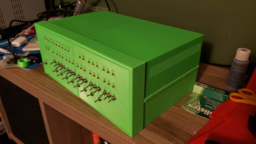
# Altair 8800 Simulator Enclosure - Altairduino If you've ever wanted to relive the glory days of the beginning of the home computer revolution, this project is for you. The Altair 8800 was announced in the Januray 1975 issue of *Radio-Electronics*, and very quickly outsold all expectations. The Altair 8800 was the driving influence behind Bill Gates dropping out of Harvard and forming Microsoft to sell software for the Altair, and Steve Wozniak was another proud owner. The Altair 8800 helped launched the microcomputer revolution, and is considered the first commercially succesful personal computer. This is a project I've been working on off and on for about 2 years, and it's finally time to upload it on here in case anyone else wants to make their own. This is a fully 3D Printed enclosure for David Hansel's Arduino Altair 8800 Simulator. You can find the instructions and bill of materials for the electrical side of things [here](https://create.arduino.cc/projecthub/david-hansel/arduino-altair-8800-simulator-3594a6). I've made a few minor changes to my version which I will detail below. I'd recommend reading through David Hanel's page and following his instructions otherwise. I designed my Altairduino so that the pieces can be printed in two parts on an Ender 3. To that end, this case is not to the same scale as a real Altair 8800. A real Altair is approximately 445mm x 432mm x 178 mm, this version is about 30% smaller at 340 mm x 220 mm x 140mm. # Design This design features a removable top panel to give easy access to the inside of the case. It is held on with a set of four 6mm x 3mm magnets. Each component is printed in two pieces and then glued together with tabs. I used CA Glue (super glue) for mine. There's also a printable front panel overlay. You'll need Legal size paper for it. I haven't applied mine yet because I haven't figured out a good way to cut out the 3mm holes for the LED's. Maybe if you have a laser cutter or a vinyl cutter that would work. Print the front bevels face down with supports as shown in the gallery. The lower case pieces should print with the bottom facing down, with supports for the pegs where needed. The top pieces print on their roof, with supports for pegs only. The fron panel should print flat on the bed. There are two versions included here. v01 is the version that I printed and is pictured in the gallery. Version one had a couple of weaknesses. Namely, the tabs that connect the front bevel to the lower case assembly snapped on me while I was connecting them. v02 has thicker tabs for that section to compensate. v01 also did not have any tabs to connect the two halves of the front bevel, relying on the lower case to line things up. An oversight there was in connecting the upper part of the front bevels together. I ended up using a lot of CA glue and just pressing it together, leaving mine a little lopsided. v02 has tabs to connect the front bevels together. For the back panel of the case I ended up using a failed print of the front panel that I had laying around. I added a couple of holes to the upper case to line up the back panel. v02 has a dedicated back panel and mounting system on the upper case. The v02 back panel has no holes in it, I leave that up to you to decide what holes you need at the back and where you want them. I think v02 is an improved design. However I don't plan on printing a new case to test the new version. So I suppose print at your own risk, and let me know how it goes. If you are printing v01, you'll need to print a second front panel to stick on the back and cover with a sheet of paper or something. With the scale change in mind, I opted to use 3mm LED's instead of 5mm LED's. I don't know how much of a difference the size of the LED's has on the brightness, but when I tested David Hansel's LED driver circuit I found them way too bright. After some trial and error, and after doing some calculations about the max current the LED's would draw compated to what the Arduino is capable of supplying, I decided to skip the LED driver circuits and have the arduino power the LED's directly through 1k ohm resistors. # Electrical Changes The 3mm LED's I used draw 1.48 mA when powered by 3.3v through a 1k ohm resistor. So with all 36 LED's turned on we get a total current draw of 53.28 mA. The Arduino Due that I used can supply up to 130 mA in total, with the individual pins being able to supply either 3 mA or 15 mA. So switching this part of the design should be safe. I've also included a Wemos D1 Mini ESP8266 microcontroller in this build to allow me to operate the Altair over WiFi. For that part of the project I used [Ondřej Hruška](https://github.com/MightyPork)'s ESPTerm firmware. It works quite well. You can find the firmware on Github [here](https://github.com/espterm/espterm-firmware). Be neater than me with the resistors. I got lazy and twisted them all together into bunches and blobbed solder onto them. Don't be like me. Let me know if you end up printing this. I'd love to hear how it goes. I've also included my (very messy) Fusion 360 project if you want to make changes. Go easy on me, it was my first time in Fusion 360. :P https://www.youtube.com/watch?v=AwXE7rRaQXA&feature=youtu.be https://youtu.be/2bMqbmSILoo
With this file you will be able to print Altair 8800 Simulator Case with your 3D printer. Click on the button and save the file on your computer to work, edit or customize your design. You can also find more 3D designs for printers on Altair 8800 Simulator Case.