AM8 Opto-Z-End Fine Adjust
thingiverse
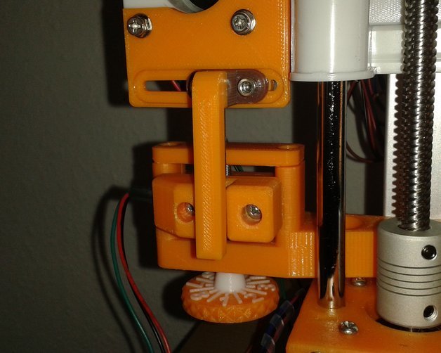
UpDate 13.09.2019: Danke an Erichfips für seine Fehlermeldung! :-) M3 Schrauben haben ein Steigung von 0,5mm und nicht 0,8mm, wie von mir angegeben. Sorry! Ich habe die SCAD-Datei und die STL-Datei entsprechend geändert. Meine Veröffentlichung ist unter http://www.thingiverse.com/thing:3382907 und https://github.com/OnkelHardy/z-opt-end-fine-adjust zu finden. Ziel dieser Entwicklung war ein optischer Z-Endschalter den man gezielt auf zB. +-50µm verstellen kann. Außerdem sollte er so stabil sein, das er sich nicht schon bei einer Berührung des Stellknopfes verstellt. Eine M3-Schraube hat eine Steigung von 0,5mm pro Umdrehung, deshalb habe ich das Stellrad von 1 bis 5 eingeteilt, mit den Zwichenschritten ergibt sich eine Einteilung von 50µm. Das Stellrad wurde mit der knurledFinishLib.scad aus http://www.thingiverse.com/thing:9095 erstellt. Die Opto-Endschalter habe ich über eBay von www.roboter-bausatz.de gekauft: - ArtikelNr.: RBS10570 - Bezeichnung: 3 Stück optische Endschalter Optical Endstop RAMPS 1.4 - CNC 3D Drucker RepRap Neben der M3-Stellschraube wird der Träger des Opto-Endschalters durch 2 M3-Schrauben und einem Halbrund links und rechts geführt. Durch dir Führung muss der Stecker des Endschalters entfernt, und die Leitungen direkt angelötet werden. Mir war in diesem Punkt eine sichere Führung wichtiger. Die Abmessungen sind von mir bewusst sehr knapp gehalten, und die Bauteile müssen mit Schleifpapier und/oder Messer einpasst werden, so das sie sich bewegen ohne zu klemmen, aber nich zu viel Spiel aufweisen. Ebenso sind die Bohrlöcher sehr knapp gehalten, und müssen auf exakt 3mm aufgebohrt werden. Wenn das ordenlich gemacht wird, wackelt oder schlappert wirklich nichts. Drei Federn halten den Träger des Opto-Endschalters auf Spannung. Die Federn habe ich einfach 3 leergeschriebenen Kugelsschreibern entnommen. Der Z-Opto-Endschalter ist für einen AM8 zur Montage an den 2040-Profilen gedacht. Ich habe 2 Halterungen entwickelt, eine (hp_Z_OptoEndBase1.stl) ist für die Montage direkt über dem linken Z-Steppermotor, und die anderee (hp_Z_OptoEndBas2.stl) für die Befestigung an der Rückseite des Profiles gedacht. Wie der Z-Opto-Endschalter montiert wird, sollten aus den beigefügten Fotos eindeutig hervor gehen. Ich habe ein RAMP 1.4 in Benutzung, bei dem Anschluss an andere Boards bitte vorher genau ermitteln. Damit eigene Änderungen ( andere Drucker etc. ) vorgenommen werden können, habe ich die Open-Scad Datei beigelegt. Druckparameter: 80% Fülldichte 0,2mm Schichthöhe 3 vertikale Konturen 3 horizontale Konturhüllen 80mm/s Druckgeschwindigkeit Support ist erforderlich. Bei einem gelungen Druck würde ich mich über einen Like sehr freuen! Gruß Hardy -------------------------------------------- UpDate 09/13/2019: Thanks to Erichfips for his error message! :-) M3 screws have a pitch of 0.5mm and not 0.8mm, as indicated by me. Sorry! I changed the SCAD file and the STL file accordingly. My publication can be found at http://www.thingiverse.com/thing:3382907 and https://github.com/OnkelHardy/z-opt-end-fine-adjust . The aim of this development was an optical-z-end-switch which can be adjusted to e.g. +-50µm. In addition, it should be so stable that it does not move when the control knob is touched. An M3 screw has a pitch of 0.5mm per revolution, therefore I have divided the setting wheel from 1 to 5, with the intermediate steps there is a division of 50µm. The setting wheel was created with the knurledFinishLib.scad from http://www.thingiverse.com/thing:9095 . I bought the opto-limit-switches on eBay from www.roboter-bausatz.de : - ArtikelNr.: RBS10570 - Bezeichnung: 3 Stück optische Endschalter Optical Endstop RAMPS 1.4 - CNC 3D Drucker RepRap In addition to the M3 adjusting screw, the carrier of the opto limit switch is guided by 2 M3 screws and a semicircle on the left and right. The plug of the limit switch must be removed and the wires soldered directly through the guide. For me a safe guidance was more important in this point. The dimensions are deliberately kept very tight, and the components must be fitted with sandpaper and/or knife so that they move without jamming, but do not have too much play. The drill holes are also very tight and must be drilled to exactly 3mm. If this is done properly, nothing really wobbles or flutters. Three springs hold the carrier of the opto limit switch in tension. I simply took the springs from 3 empty ballpoint pens. The z-opto-limit-switch is intended for an AM8 for mounting on the 2040 profiles. I've developed 2 mounts, one (hp_Z_OptoEndBase1.stl) is for mounting directly above the left Z-Stepper motor, and the other (hp_Z_OptoEndBas2.stl) is for mounting on the back of the profile. How the z-Opto-limit-switch is mounted should be clear from the attached photos. I have a RAMP 1.4 in use, please check the connection to other boards beforehand. So that own changes ( other printers etc. ) can be made, I enclosed the Open-Scad file. Print parameters: 80% filling density 0,2mm layer height 3 vertical contours 3 horizontal contour envelopes 80mm/s Print speed Support is required. With a successful print I would be very happy about a Like! Greetings Hardy
With this file you will be able to print AM8 Opto-Z-End Fine Adjust with your 3D printer. Click on the button and save the file on your computer to work, edit or customize your design. You can also find more 3D designs for printers on AM8 Opto-Z-End Fine Adjust.