An Introduction to Kinematic Coupling
pinshape
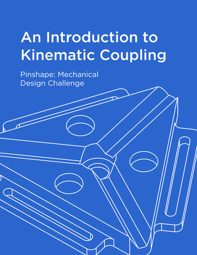
Dear Pinshape Users, I'm excited to share my submission for the Pinshape Mechanical Design Contest, which highlights a fascinating and often underappreciated mechanical concept: kinematic coupling. My tutorial-based project aims to educate you on the principles of kinematic coupling while providing hands-on experience throughout the process. The three lessons in this series cater to different skill levels, from beginner to advanced, and focus on teaching the theory behind kinematic coupling and demonstrating its application in a real-world scenario: optomechanics. The sequence of tutorials follows the contest's notion that 3D printing is rapidly advancing towards end-use part production. A comprehensive .PDF manual accompanies this submission, offering step-by-step instructions, educational information, and assembly photos for each tutorial. Quick Overview: Kinematic coupling is a method of precisely constraining physical objects together to ensure reproducible certainty of location. This precision engineering technique is utilized in various applications, such as robotics, tooling/fixturing, and optomechanics. Beginner Tutorial: Start by understanding the basic theory of kinematic coupling through 3D printing and assembling a Maxwell and Kelvin model. Print two copies of Kelvin_and_Maxwell_top.stl with flat surfaces facing down and one copy each of Maxwell_bottom.stl and Kelvin_bottom.stl, also with flat surfaces facing down. Intermediate Tutorial: For this tutorial, print Lens_holder.stl and Lens_mount.stl using FDM printer settings (Slic3r, 0.2mm layer height, 30% infill, PLA, CF PLA, or Nylon). Print the pin slots of Lens_mount.stl facing down on the bed. Advanced Tutorial: Using a SLA printer with Tough Resin and 0.1mm layer height, print Optic_piece_advanced.stl without building supports that contact the biconvex surfaces. Do not build supports for Lens_holder_advanced.stl or Locking_ring.stl that contact the threaded section.
With this file you will be able to print An Introduction to Kinematic Coupling with your 3D printer. Click on the button and save the file on your computer to work, edit or customize your design. You can also find more 3D designs for printers on An Introduction to Kinematic Coupling.