Anet A6 3D/BL Touch Sensor Holder
thingiverse
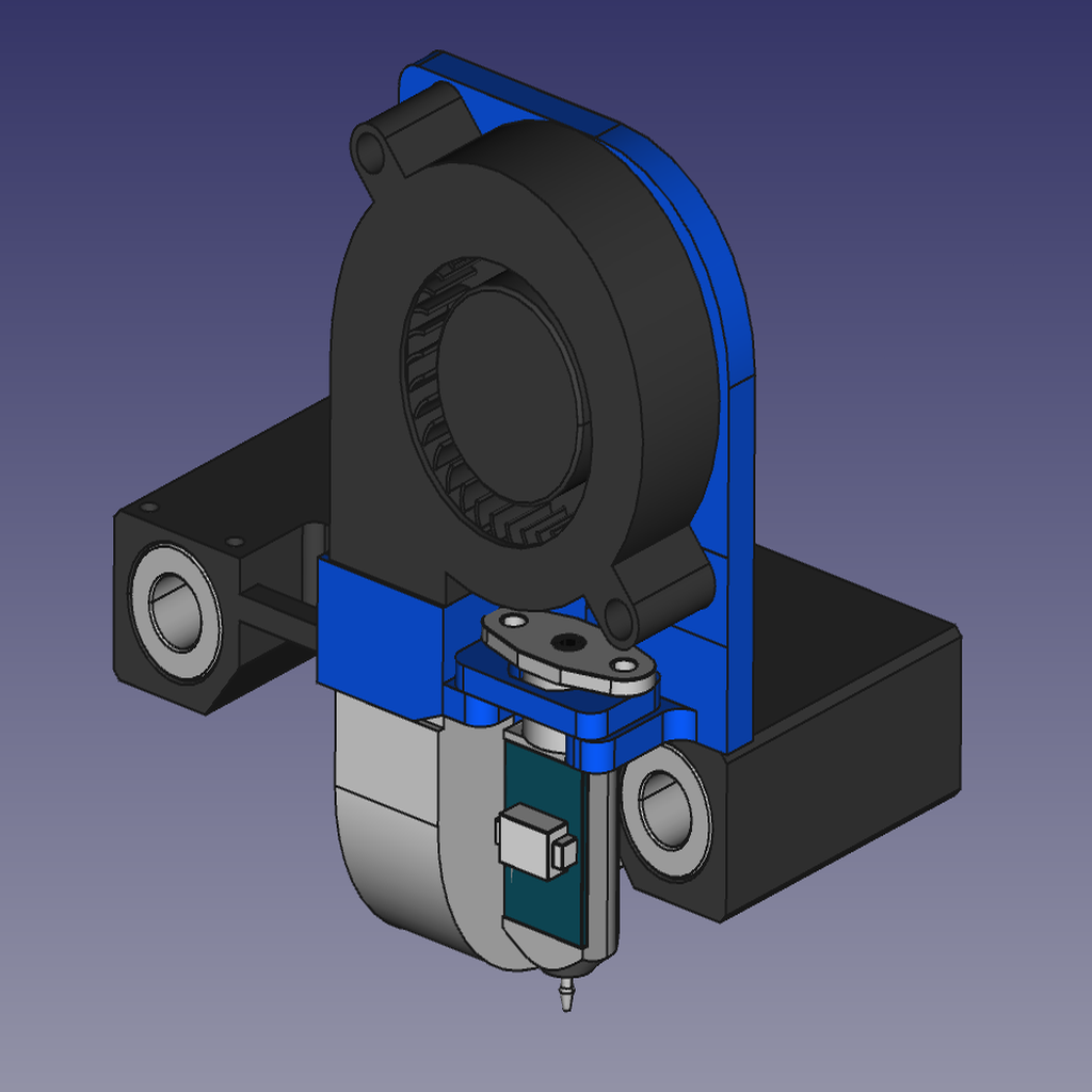
Since I was fed up with the constant leveling, I decided to install a 3D touch sensor. Once again, I was not happy about the solutions found on Thingiverse. The sensor was either too far away from my nozzle or it shortened the range of motion in the X-axis. For my solution, I moved the part fan a little upwards and created space for the sensor. So that you don't have to install an extension for the duct, I integrated it directly into the holder. __Mechanical construction__ The holder replaces the original component fan holder. There are two versions: the standard version and a version with built-in cable guidance. The space for the sensor is very limited, on the fan side the sensor even has to be sanded down a little to fit. There is also only a gap of 0.5mm between the sensor and the 8 mm rod. To adjust the distance between sensor and nozzle in height, I provided three spacers. I used the 2mm version myself. I used the supplied M2.5 x 15 for screwing. A screw has to be shortened to a length of 10mm. _Printer settings:_ Material: PLA Resolution: 0.2mm Wall thickness: 1.2mm Top/Bottom thickness: 0.8 - 1.2mm Infill: 30%, Grid Support: yes, but you can try without it. The .stl-files are already correctly oriented for printing. __Electrical components__ The 3D-Touch sensor was delivered with a 5-pin connector and an 80cm extension. I used the connector for a different purpose and used it as a connector on the mainboard. Therefore, I had to solder the extension cables together. I also replaced the DuPont connector with a 3pin XH2.54 connector.  Since the mainboard doesn't have a direct connector for the servo pin, you have to improvise a bit. I found several possible solutions, but I didn't really like any of them. I have an Anet Board V1.5 leaving space for a 2.1x5.5 socket for an external supply voltage. I used the GND solder pad to solder two pins of the 5-pin connector. Here is the connection diagram for the LCD12864 display (the LCD2004 display needs another pin!) and my wiring in pictures:  __Software__ Since Auto-bed leveling does not work without the appropriate software settings, there are still several settings in the Configuration.h in Marlin to be set. In order to have enough memory to enable autoleveling at all, the Optiboot-loader should be installed. Alternatively, you can search for the keyword PROGMEM and try to disable options there. My configuration settings for Marlin 1.1.9: //======= Z Probe Options ======= #define Z_MIN_PROBE_USES_Z_MIN_ENDSTOP_PIN #define BLTOUCH #if ENABLED(BLTOUCH) #define BLTOUCH_DELAY 100 #endif #define X_PROBE_OFFSET_FROM_EXTRUDER -28 #define Y_PROBE_OFFSET_FROM_EXTRUDER -22 #define Z_PROBE_OFFSET_FROM_EXTRUDER -1.05 #define Z_CLEARANCE_DEPLOY_PROBE 15 // set up at least 15 #define Z_CLEARANCE_BETWEEN_PROBES 10 // set up at least 10 //====== Bed Leveling ======= #define AUTO_BED_LEVELING_BILINEAR // Set the boundaries for probing #define LEFT_PROBE_BED_POSITION 30 #define RIGHT_PROBE_BED_POSITION 190 #define FRONT_PROBE_BED_POSITION 30 #define BACK_PROBE_BED_POSITION 190 //======= Additional Features ====== #define EEPROM_SETTINGS #define DISABLE_M503 //====== Extra Features ====== /** * R/C SERVO support */ #define NUM_SERVOS 1 #define SERVO_DELAY { 300 }
With this file you will be able to print Anet A6 3D/BL Touch Sensor Holder with your 3D printer. Click on the button and save the file on your computer to work, edit or customize your design. You can also find more 3D designs for printers on Anet A6 3D/BL Touch Sensor Holder.