Anet A8 3D-Touch Mount

Anet A8 3D-Touch Mount

thingiverse

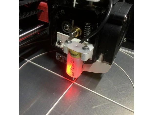
This is a mount for the Geeetech 3D-Touch / BLTouch Sensor for Anet A8 printers. This design is meant for people which do not use an extruder cooling fan and heatsink. (Both are not really needed as shown by multiple experiments of different users. Please no discussions about that ;-) I included the Fusion 360 file which makes it easy to modify if needed. The mount fits right onto the side of the extruder using the original (shorter) screws. It has little holes for the nuts of the sensor screws to make assembling easy. After assembling the sensor is very stiff connected to the j-frame. It will hardly move or bend on usage. I printed the mount with BDP (GreenTec) filament but I think normal PLA will do. The sensor distance should fit for the standard A8 extruder out of the box. I also included some information on how to connect the sensor to the Anet motherboard. The first two images show the sensor mounted to the extruder. The second two images are showing the "draft" wiring and the last three images show my final wiring. It uses the "LED pin" which is an unused pin on the A8 (using the stock 5 button 2004 LCD). That is the third wire counted from below (where the red marker is on the cable). I simply spliced the cable and cut that wire. This will be the servo signal (yellow). On the A6, you can use wire no. 7 and FW pin 29. I could verify that with the A6 display I have available. The +5V (red) and GND (brown/black) are available at the z-end-stop connector as is the signal itself (white). You can simply connect the black and brown wire of the sensor to the GND from the z-end-stop socket. This leaves you with 4 instead of 5 wires from the sensor to the board. On the first of the second two images you can see how I used some patch cables and a wire clamp to draft the connection at the board. In the second of the two images you can see the wiring at the sensor. After everything worked well I have chosen an old usb mouse cable. Those have exactly 4 wires. I used green for the sensor, red for +5v, black for GND and yellow for the servo signal (originating from the LCD cable). I crimped a fitting connector for the z-end-stop socket and a single connector for the connection to the spliced LCD cable. I also soldered the other end of those 4 wires directly to the PCB inside of the sensor. Soldering is not needed and can be a pain. Beware not to destroy your sensor if you do it. You can see the result in the last three images. Setting up SkyNet3D / Marlin (the firmware) is pretty straightforward. Besides the entries for the auto bed levelling you need to make the following entries: #define BLTOUCH #define SERVO0_PIN 27 #define X_PROBE_OFFSET_FROM_EXTRUDER -20 #define Y_PROBE_OFFSET_FROM_EXTRUDER -15 #define Z_PROBE_OFFSET_FROM_EXTRUDER 0 #define Z_MIN_PROBE_ENDSTOP_INVERTING false I also used: #define Z_CLEARANCE_DEPLOY_PROBE 5 #define Z_CLEARANCE_BETWEEN_PROBES 5 #define LEFT_PROBE_BED_POSITION 20 #define RIGHT_PROBE_BED_POSITION 200 #define FRONT_PROBE_BED_POSITION 20 #define BACK_PROBE_BED_POSITION 200 After mounting and uploading the new firmware you can test you sensor: M280 P0 S10 ; pushes pin down M280 P0 S90 ; drags pin up M280 P0 S120 ; does selftest (pin up/down continuously) M280 P0 S160 ; reset alarm M280 P0 S60 ; switch triggering test mode ; move pin at the sensor up or down manually M119 ; reports state of the endstop ; pin up (LED on) z_min should read TRIGGERED ; pin down (LED off) z_min should read open If your sensor does not selftest but blinks directly or after some few alternating motions you need to adjust the screw in the top of the sensor. One of the allen wrenches which are part of the printer does fit right in. Lose the screw until the light went off, then fasten the screw until it is lit again. I needed some time to find the sweet sport. Using selftest and reset alarm until it worked well. Finally you can try a G28 command. If everything is OK it will probe twice in the middle of the bed. The tip will go down and up again as soon it touches the surface of the bed. If not you need to check cables and settings. To adjust the z offset I use the following easy and pretty failsaife procedure: ; preheat for working temperatures (M502 ; optionally reset to firmware settings) M851 Z0 ; reset any z-offset G28 ; home all G1 X110 Y110 ; move nozzle in center M211 S0 ; disable software endstop ; now move your nozzle manually onto the bed such that it (strongly) grips paper. G92 Z0 ; tell the printer that this is Z = 0 G30 X110 Y110 ; move the sensor over the center and let it trigger ; note what z position G30 reports, that, negated, is your z offset M851 Z-1.23 ; register that z offset (here 1.23 as example) M500 ; store those values into the EEPROM You may want to do some G30 X110 Y110 commands to validate how well your sensor works. It should report the same values +/- 0.0x. You can also enable Z_MIN_PROBE_REPEATABILITY_TEST in the firmware and use M48 L10 P8 V4 to let it test repeatability at the same point with a lot of fake movement in between probes. There are occasions where the sensor after power on gives an error with the G28 command for no obvious reason. I found that the sequence: M280 P0 S160 ; Reset 3D-Touch G4 P500 M280 P0 S10 ; Pin out G4 P500 M280 P0 S90 ; Pin back G4 P500 Before the G28 command will reset the sensor in a way that it will alway (tm) work. UPDATE: I added an alternative design "Distant" for the excellent "Mistral 2" cooling fanduct. This needs slightly changed firmware settings as follows: #define X_PROBE_OFFSET_FROM_EXTRUDER -26 #define RIGHT_PROBE_BED_POSITION 194 Some links to more information: Marlin and auto levelling: http://marlinfw.org/docs/configuration/configuration.html BL Touch: https://www.indiegogo.com/projects/bltouch-auto-bed-leveling-sensor-for-3d-printers 3D-Touch: http://www.geeetech.com/wiki/index.php/3DTouch_Auto_Leveling_Sensor SkyNet3D download: https://www.facebook.com/skynet3ddevelopment/?fref=ts Anet A8 Marlin port sources: https://github.com/SkyNet3D/Marlin "Just Blinking" ? Read this: http://www.geeetech.com/forum/viewtopic.php?f=27&t=18263 Thanks to "Tobi As" for the wiring overview image! Print Settings Printer: Anet A8 Rafts: No Supports: No Resolution: 0,2 Infill: 30% Notes: I printed it topside down to get best stiffness. The model was adjusted to print without supports.

Download Model from thingiverse

With this file you will be able to print Anet A8 3D-Touch Mount with your 3D printer. Click on the button and save the file on your computer to work, edit or customize your design. You can also find more 3D designs for printers on Anet A8 3D-Touch Mount.