Anet A8 and A8 Plus X axis carriers
thingiverse
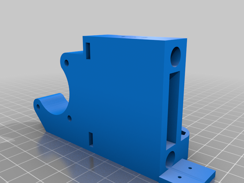
This is a printable set of replacement Z axis bearing carriers for the X axis gantry assembly for the Anet A8 and Anet A8 Plus 3D printers. These printers ship now with injection molded carriers, which work fine in these printers default configurations. I designed these mostly for experimentation purposes. While the 45mm Z axis steel bearings on my Anets are still in relatively good shape, every other bearing on both printers are terribly worn, and I've been wanting to experiment with the Igus plastic bushings. I wanted to install a relatively painless method for switching between bearings and bushings for longevity and print precision tests. The injection molded carriers that come with these printers are a very tight friction fit to the bearings, which presents no problem for the steel bearings, however, they distort the Igus bushings terribly causing them to bind severely on the guide rods. The 45mm bearings or bushings are held in place with two 15mm internal snap rings as opposed to compression from the carriers. The aluminum bearing carriers for the X and Y axis that used to come with the Anet A8 just a few years ago have the 15mm internal snap rings, so if you've replaced any of those bearings in the past, you may have these snap rings already. My two Anet's came with injection molded plastic carriers all the way around, so I had to order the snap rings. A bag of 100 snap rings cost me U.S. $7.13. The standard replacement carriers here, "X_Carrier_Right_V1.1.stl" and "X_Carrier_Left_V1.1.stl" print easily as they are oriented in the STL's without any supports. I included an additional right side carrier titled "X_Carrier_Right_V1.1TBS.stl". The "TBS" is for "tensioner back stop". The "TBS" version of the right side carrier has a provision for a built in tension adjuster. There is an accompanying file, "X_Carrier_Tensioner_V2.stl" which is the part that will hold the idler bearing. While this is not a remix in the classic sense, I did design these to have the look of AVZ's "Anet A8 X Axis Printed Pieces -Idler and Motor Holders". A few of the measurements used in my model come from his while others come from the injection molded parts that shipped with my Anet A8. The positioning for the screw holes that attach the brass nuts to these parts was taken directly from AVZ's model. The X tensioner uses the two bearing sandwich and M3 screw that came with the Anet A8 but will also require a M4 X 50mm hex cap screw, two M4 nuts and a M4 washer to be complete. To assemble the tensioner, slip the 50mm M4 screw through the opening in the fork of the tensioner, then attach a M4 nut to the opposite end and tighten it. Then, using the M3 hardware and bearings from the original right side carrier, insert the two bearings into the fork, run the screw through the fork and bearings, install the nut and tighten the screw while orienting the nut so that it will slip into the captive hole. Either end of this model requires two 15mm internal snap rings. If you're interested in experimenting with the Igus or even printed bushings and need the carriers for the LM8UU 24mm long bushings, I have a model for the bed and carriage bearings as well at: https://www.thingiverse.com/thing:6025578 Shamefully, while this is actually the 3 iteration of this design, I had to walk it back in part because of a measurement I'd changed between the bearing holder portion and where the brass nut connects. I measured 22mm center to center on the two holes, but when I was putting my printer together with the new parts, I found I had to open that distance to 23mm on center so that my guide rods would slip easily into the holes for the motor mounts. It turns out there's a millimeter of slop where the motors attach to that bracket and I was somehow able to mount both motors fully to the insides. Oops... So after making, printing and installing the version 2.0 parts, everything seemed fine, until... I printed a tall model. The printer started binding on the Z axis just shy of 300mm. I then measured the top mounting plates and found that the holes have 22mm centers. Apparently, the split in the original injection molded carriers offered enough leeway that I hadn't encountered those problems for as long as I've had the A8 Plus. Another change I made was to the "X_Carrier_Right_V1.1TBS.stl" file by adding a backstop for the X axis guide rods. While I'd never used a tensioner before on either my A8 or A8 Plus, I assumed that my tensioner design was just going to be a dandy. It was not... :( It turns out there's a good reason most of the tensioners for these printers push against the guide rods. Applying just a little more tension than is necessary will cause both carriers to move in on each other which results in the Z rods and leed screws bowing inward. Both my A8 and A8 Plus had just shy of 1mm of rod showing past the right side carrier, so I made the cavity in the backstop 1mm deep. Theoretically, one could tighten the tensioner until something breaks with version 1.1. :) I
With this file you will be able to print Anet A8 and A8 Plus X axis carriers with your 3D printer. Click on the button and save the file on your computer to work, edit or customize your design. You can also find more 3D designs for printers on Anet A8 and A8 Plus X axis carriers.