Anet A8 Reduce Stepper Current
prusaprinters
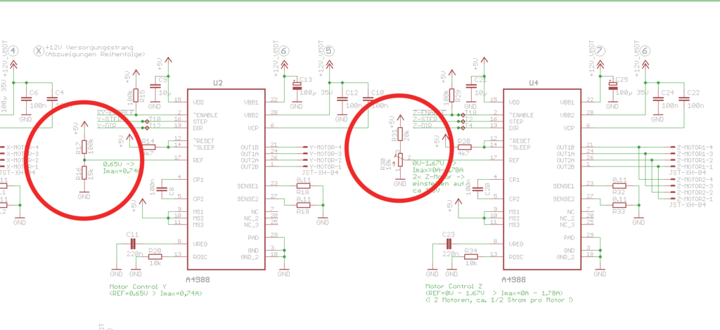
<h3>Important</h3> <p>There is a chance you might destroy either your board or your stepper motor(s) when trying this!</p> <p>You need to solder resistors on your board. So if you dont know how to solder - sorry this guide is not for you.</p> <p>Furthermore, you should be able to measure voltages and resistances and be able to understand the marked parts in the schematic.</p> <h3>What is the problem?</h3> <p>If you own a (older) Anet A8 board chances are that you can not change stepper currents or only the current of the z-axis steppers.</p> <p>Check <a href="https://3dprint.wiki/reprap/anet/electronics/mainboard">https://3dprint.wiki/reprap/anet/electronics/mainboard</a> for more details.</p> <p>The default current for the steppers is quite high on the Anet A8, which causes the stepper motors to get quite hot and produce a lot of noise.</p> <h3>How to fix this?</h3> <p>Searching the internet i found the schematics for the board here: <a href="https://github.com/ralf-e/ANET-3D-Board-V1.0">https://github.com/ralf-e/ANET-3D-Board-V1.0</a></p> <p>As can be seen on the schematic the stepper drivers use a voltage divider with a 100kohm and a 15kohm resistor.</p> <p>By replacing the 15kohm resistors (the one attaching to ground) with a smaller resistor we can reduce the current sent to the steppers.</p> <p>Using the voltage divider calculator <a href="http://www.ohmslawcalculator.com/voltage-divider-calculator">http://www.ohmslawcalculator.com/voltage-divider-calculator</a> you can calculate the desired resistance.</p> <p>Note: If you input the original values (5V, 100kohm, 15kohm) you get 0.652V - this is the value you can also see in the schematic.</p> <p>In order to get the desired resistance you need to know which voltage you want instead of the 0.652V.</p> <p>In order to get the desired voltage you can test with the z-axis which can be adjusted using the potentiometer.</p> <p>For this you just connect your x- or y-axis to the z-driver, adjust the voltage such that the axis still moves properly (you need to move z!) and measure the voltage of the potentiometer to ground.</p> <p><strong>Important</strong>: before you change the z-driver voltage make sure to measure the original voltage and remember it. You want to reset the voltage to that value afterwards.</p> <p>Also, before you test your x- or y- axis on the z-driver make sure to reduce the voltage at least to 0.65V. The z-driver usually drives two stepper motors, so it is set to a higher voltage by default.</p> <p>Once you figured out the desired voltage you can calculate the required resisance using the voltage divider calculator. Just remove the 15kohm and set the output voltage and press calculate. I added an image with a desired output voltage of 0.4V - as can be seen in this case the desired resistance is around 8.7kohm.</p> <p>Now you can either replace the 15kohm resistor with a resistor of the desired size or add a second resistor in parallel.</p> <p>In the first case you can just use the calculated resistance - using the 0.4V example, you just replace the 15kohms with 8.7kohms.</p> <p>In the second case you need to calculate the size of the resistor to put in parallel.</p> <p>You can use the parallel resistance calculator: <a href="http://www.sengpielaudio.com/calculator-paralresist.htm">http://www.sengpielaudio.com/calculator-paralresist.htm</a></p> <p>Just input 15kohm as R1 and the desired resistance (e.g. 8.7) as Total and press calculate.</p> <p>In the example of 8.7kohms the parallel resistor needs to be around 20kohm.</p> <p><strong>Important</strong>: After replacing or adding the resistor make sure you get the correct resistance to ground. Unplug the stepper motors and the board for measuring the resistance.</p> <p>If you don't get a correct value check the solder joints. If the resistance is too high or there is no connection at all you might end up frying either your drivers or your stepper motors!</p> <p><strong>Note</strong>: i haven't tested putting resistors in parallel when i performed this. I just replaced the original resistor with a new one.</p> <p>However, in hindsight adding a second resistor is probably safer than replacing the original one. You'll probably understand what i mean if you look at the image of my board :-P</p> <p>I use this to reduce the currents for the stepper motors for my C3D-Rom Driver Printer <a href="https://www.thingiverse.com/thing:4315542">https://www.thingiverse.com/thing:4315542</a></p> Category: 3D Printing
With this file you will be able to print Anet A8 Reduce Stepper Current with your 3D printer. Click on the button and save the file on your computer to work, edit or customize your design. You can also find more 3D designs for printers on Anet A8 Reduce Stepper Current.