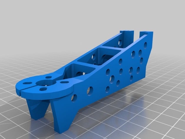
Another Arm for HFM Totem Q250 and Eachine 250 FPV Racer
thingiverse
Update 3/20 Rev B removed one hole. Lowered top line to increase clearance for 6 inch prop. Update 3/19 I added a revision of the arm with the 3mm pushup for the Eachine Racer. Most notable are the changes in the side panels, which hopefully will reduce the chance of breaking at the lower mounting feet. The space between the arms is large enough to fully contain the standard ESC now. The holes were added to reduce the weight. Maybe there are too many, maybe more can be tolerated? I didn't include the sketchup file; there may be other things I want to try before finalizing it. I haven't printed it, but here are the settings I would use: .4mm nozzle, .3 layer height 5 bottom layers 5 top layers. 4 perimeters. 0 infill Uncheck the EXTERNAL PERIMETERS FIRST box (in slic3r) so external perimeters print last (unsupported bridges will likely be better) Bed placement: 180, -11.6, 0 The previous, similar version here was over 4 grams lighter than the original (plus spacers). This one will be somewhat heavier. UPDATE 3/17/16 I uploaded a version of the arm that was modified to increase the offset in the top and bottom holes to 8mm. This version is intended for use with sheet metal screws, or machine screws threaded into the plastic. There are two versions; one version is the normal height and requires use of two spacers for the Eachine Racer. The other version is 3 mm taller and can be used without spacers in the Eachine Racer. The use of #4 sheet metal screws requires that the hole in the top and bottom plate be enlarged or the threads removed below the screw head so it can turn freely in the hole, once the threads have cut down through the mounting plate. If you enlarge the holes and later decide to use a factory arm, then you should probably use button head screws rather than the cap screws furnished with the item. The enlarged hole size may cause damage to the top and bottom plates in a crash if a cap screw is used with an enlarged hole. I printed a sample in PLA and it fits as it should. It can be printed without or with infill. Without infill gives some empty space between the inner and outer shells that MIGHT help in a crash. It is sized for printing with a 0.4 mm nozzle, .3 mm layer height and 3 perimeters for space between the shells. About any infill will result in a mostly solid print. I removed the original arm from thingiverse.com, i.e. the one with the 5 mm offset and designed for the original threaded inserts. I will not be replacing it. There may be additional changes. The weak point of the original may have been fixed, but another is surely going to show up. IMPORTANT The dimensions of the mounting holes in the original submission do not match the arms I purchased. The difference between the axis of the top and bottom mounting holes is 5.1 mm in the oritinal model and I measured 8 mm in the factory arms I have. Anything printed with the original file might be usable, but the sample I printed caused the arm to be tilted up from the other arms mounted on the quad due to the shorter distance between top and bottom mounting holes in the model. . 3/15 1325 UCT -7 **** My thanks to GuruX for an excellent copy of the original arm. I have been looking at this since before I got my printer and only recently felt comfortable enough with Sketchup to make some of the modifications I wanted to try. This is a work in progress. I printed a nice copy in PLA that I'll give a try. It is a bit lighter and more flexible in PLA than the original. ABS should take a bigger hit and keep going. I made the following changes from the original: Increased the width of the landing feet below the motor. Mine are always getting banged up when landing on concrete and rocks. Added a cut through the center of the motor mounting surface so the arm can be changed without having to unsolder anything. Added fillets to the vertical stiffeners in the arm. There is a bad case of stress concentration here; I have had several arms that broke cleanly at these points with a crash that wouldn't have stopped other quads. Added one more perimeter of material around the holes where the threaded bushing inserts. They were a bit thin on two sides w/o infill. Removed some material at the back that (IMO) that contributes to the weight, but not the strength. Print Settings Printer Brand: RepRap Printer: Prusa I3 Rafts: No Supports: Yes Resolution: 0.4 mm nozzle. 0.3 mm layer height, 3 perimiters min Infill: not required Notes: The following are suggestions; I haven't printed it in ABS yet, only PLA. I used 3 perimeters and zero infill for a first try. If you don't use infill, there will be voids in the center of some layers, but I don't think the strength will be compromised significantly, in most places. With the above settings, 6.5 meters of 1.75 filament are required including the support material. Before slicing, position the object with the top facing down and tilting at about -11 degrees, depending upon which one you are printing. This puts the both ends of the arm close to the bed and permits minimum support structure underneath the arm. My second print was the arm with the increased height. It looked good, and the mounting holes match the factory arms. I only replaced one arm, but all four feet set on a flat surface, unlike the previous sample. It was easier to flex this arm (in PLA) than the original, which, in my experience, breaks upon light impact. Infill and some thickening of the bottom mounting pads might be required as it might not be strong enough as it is. Post-Printing After printing, sand the extrusion flash off the mounting pads. It is a tricky to hold the arm so the surface remains flat and parallel to the top and bottom plates. A block under the free end would help while sanding. Use a soldering iron to gently heat whatever screw you are using before trying to thread it into the arm. You can tell when it cools as it becomes harder to drive the screw. Reheat as necessary and drive the screw within a couple mm of its final position. I used 0.5 inch SAE #4 sheet metal screws. A smaller diameter metric or SAE sheet metal screw would be preferable, if available. After threading, remove the screws and sand the mounting surface to remove the material that was thrown up when the thread was cut. How I Designed This modified the Sketchup file furnished with the original.
With this file you will be able to print Another Arm for HFM Totem Q250 and Eachine 250 FPV Racer with your 3D printer. Click on the button and save the file on your computer to work, edit or customize your design. You can also find more 3D designs for printers on Another Arm for HFM Totem Q250 and Eachine 250 FPV Racer.