Anycubic Photon Mono SE air filtration system
thingiverse
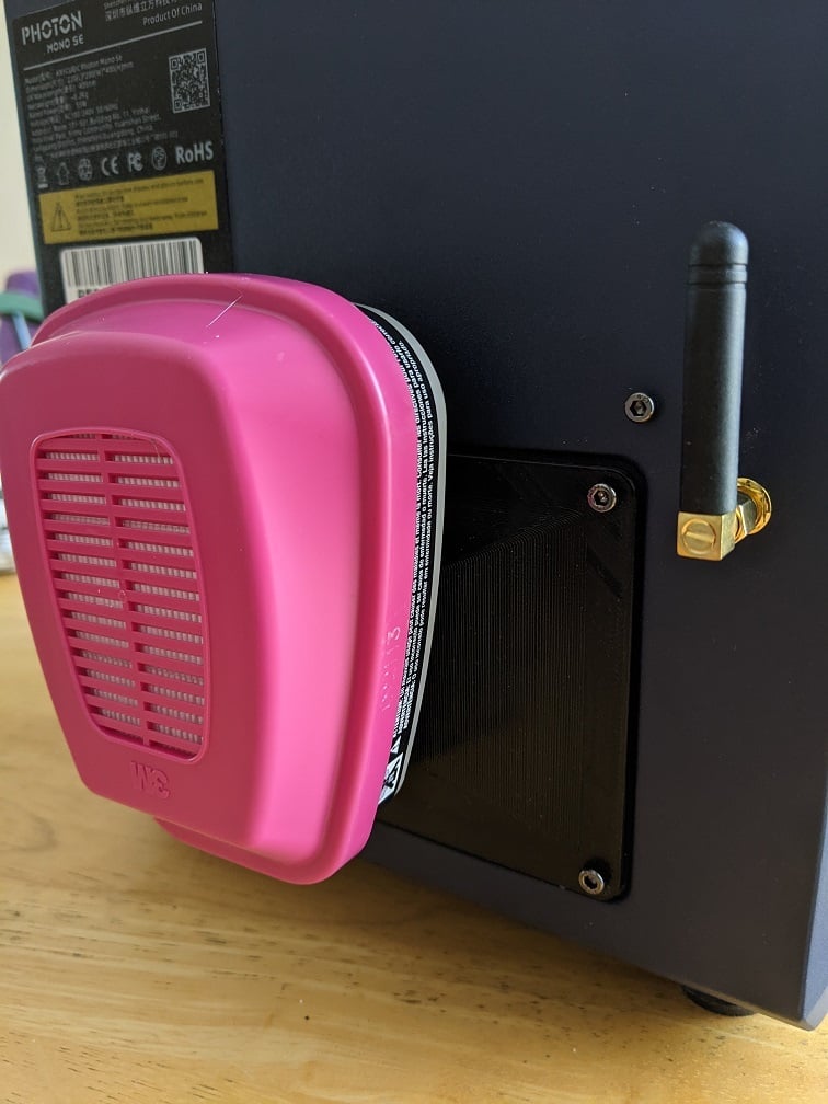
Filtration system for Photon Mono SE. Inspiration taken from [here](https://www.thingiverse.com/thing:3681435) which was made for the regular Photon. The factory Photon Mono SE advertises a "carbon filtration" system, but in reality it just consists of two really small fans (30mm x 30mm, similar size to the ones for cooling Raspberry Pi's) that pull air from the build area, through some activated carbon sponge filters, to the bottom printer cavity. This bottom printer cavity has a larger fan for cooling the UV lamp that pushes air out the bottom of the printer. <img src="https://cdn.shopify.com/s/files/1/0245/5519/2380/files/7_UV_Cooling_System.jpg?v=1598506614" height="300" width="400"> **Some issues here:** \- Build area fans are pretty weak. \- Activated carbon sponge filters can’t be easily changed out. This system replaces the build area fans, and reroutes airflow to the back of the printer through a respirator cartridge. **fanshroud.stl, backplate.stl**: Printed with 1.2mm shell thickness, 20% infill and supports touching buildplate. **bottomcover.stl**: Printed with 1.2mm shell thickness, 20% infill and no supports **Some disclaimers:** \- This setup does not completely eliminate all resin fumes, please still keep your printer in a well ventilated area. \- Involves opening up the Photon Mono SE to replace some of the fans, so continue at your own discretion. Below is a rough list of steps/materials I took to replace the fans (a PDF version is also included in the files). ## Materials: (linked are the exact ones I bought) \- [5015 radial blower fans](https://www.amazon.com/gp/product/B079BMX2S6/ref=ppx_yo_dt_b_asin_title_o00_s00?ie=UTF8&psc=1) (2) \- [6010 brushless fan](https://www.amazon.com/gp/product/B07GX86CJN/ref=ppx_yo_dt_b_asin_title_o00_s00?ie=UTF8&psc=1) (1) Note: All the fans are 12V DC, 0.1A \- [3M 60921 P100 respirator cartridge](https://www.amazon.com/gp/product/B00BT2SWTE/ref=ppx_yo_dt_b_asin_title_o00_s00?ie=UTF8&psc=1) (1) 60921 has both activated carbon and P100 filter. Additionally, any respirator cartridge that can fit 6000, 7000, FF-400 Series with a bayonet-style attachment should be compatible, try to get one that filters out organic vapors. \- M4 x 25mm screws (2), M4 hex nuts (2) (I got away with using M4 x 30mm screws) \- M3 x 15mm screws (4), M3 hex nuts (4) \- [activated charcoal sachets](https://www.amazon.com/dp/B0149GP7IU?psc=1&ref=ppx_yo2_dt_b_product_details) (2) (optional) **Tools:** \- M2, M2.5 Allen keys/hex screwdrivers \- needle nose pliers \- hot glue \- superglue May also need: \- solder/soldering iron, shrink tubing OR XH2.54 JST male-female extension cable (see step 5.5) ## Assembly: **1. Unscrew the build area fans. Leave them attached for now.** **2. Open up the bottom cavity of the printer.** **TURN OFF** and **UNPLUG** your printer. See this [video](https://www.youtube.com/watch?v=N1wSEBeXhtg&ab_channel=AnycubicSupport) (just the first minute is relevant) on what screws to remove. \- Remove the motherboard from the printer, but keep it on the metal L-bracket. Nothing from the motherboard needs to be unplugged for now. \- Keep track of which screws go where! \- Also remove the UV lamp so it's easier to access the carbon filters (see image below for screw location). <img src="https://i.imgur.com/LyOWsFY.jpg" height="300" width="400"> **3. Remove the carbon filters.** They are cube shaped, so the best method was just using the pliers from the bottom cavity (and an Allen key pushing down from the build area) to rip off small chunks before it was small enough to shimmy out of the hole (below is where the carbon filters can be removed from). <img src="https://i.imgur.com/T4AyrYo.jpg" height="400" width="300"> \- Be careful not to rip any wires off the motherboard. **4. Unplug the build area fans from the motherboard.** You may need to peel off the red wax on the plugs. For me, the fans were at slots FAN2 and FAN3, but just follow the wires (save these for another project :) ). **5. Unscrew and flip the UV lamp cooling fan.** Keep it plugged into the motherboard. At this point the UV lamp can be reattached as well. See image below for how the fan blades should be orientated. Air should now be moving up from the bottom of the printer. <img src="https://i.imgur.com/j5qeOig.jpg" height="400" width="300"> **5.5. Extend the wire on one of the 5015 radial blower fans.** For one side, the wire is just long enough to plug into the motherboard, but there isn’t enough slack to easily attach the fan to the 3D printed fan shroud later. I would recommend extending it with either solder/soldering iron (and insulate exposed wires with shrink tubing) or a XH2.54 JST male-female extension cable. **6. Attach the 5015 radial blower fans.** Feed the wires through the filter housings in the build area and down into the bottom cavity of the printer. Plug each fan into the motherboard, note which side the power (+/red) and ground (-/black) wires should be on, I had to flip the plugs on my fans. <img src="https://i.imgur.com/j2DXHbc.jpg" height="300" width="400"> Use the M4 x 25mm and M4 hex nut to attach the fan to the fanshroud.stl (see image below). Then attach the fan shroud to the filter housings with the screws that held down the old build area fans. The left fan was flipped so that the blades were more effective at pulling in air. <img src="https://i.imgur.com/4oAi548.jpg" height="400" width="300"> <img src="https://i.imgur.com/3f5xgfb.jpg" height="400" width="300"> <img src="https://i.imgur.com/VBjMCvG.jpg" height="400" width="300"> **6.5. Insert activated carbon sachets.** Optional if you want extra filtering (these can be changed out as needed). Roll up a sachet lengthwise as seen in the picture below. It should fit snugly in the circular hole from the bottom cavity. <img src="https://i.imgur.com/afH88wB.jpg" height="300" width="400"> <img src="https://i.imgur.com/m6ykIg8.jpg" height="300" width="400"> **7. Attach the 6010 fan.** Superglue in M3 hex nuts into the posts of the back plate. <img src="https://i.imgur.com/G2kvsuv.jpg" height="300" width="400"> Use M3 x 15mm screws to attach the fan to the backplate.stl. See image below for how the fan blades should be orientated. Plug the fan into the FAN0 slot, again note which side the power (+/red) and ground (-/black) wires are on. After all the fans are plugged into the motherboard, I would recommend hot gluing the plugs in place. <img src="https://i.imgur.com/Vk7R1jy.jpg" height="300" width="400"> **8. Close up some of the openings at the bottom of the printer.** Print out two bottomcover.stl, and two bottomcover.stl but mirrored. Cover the other openings except for the circular opening (as seen below). I then hot glued around the edges of the 3D printed covers (the hot glue can be easily peeled off from the metal printer cover). <img src="https://i.imgur.com/SPvLovH.jpg" height="300" width="400"> <img src="https://i.imgur.com/iGkACAI.jpg" height="300" width="400"> **9. Reassemble the printer.** Refer to the video above. Hopefully no screws have been lost :) When screwing on the back plate, note the orientation of the bayonet attachment (see image below). <img src="https://i.imgur.com/fPJP8gU.jpg" height="300" width="400"> **10. Attach the 3M 60921 respirator cartridge.** <img src="https://i.imgur.com/9vIyHGB.jpg" height="400" width="300"> **Helpful tips:** \- Every now and then (especially after attaching the fans to the motherboard) do an exposure test to check that the fans are working/pushing air in the right direction. The fans only turn on when the UV lamp is on. \- Be sure to power off and unplug the printer when working in the bottom cavity of the printer.
With this file you will be able to print Anycubic Photon Mono SE air filtration system with your 3D printer. Click on the button and save the file on your computer to work, edit or customize your design. You can also find more 3D designs for printers on Anycubic Photon Mono SE air filtration system.