ApplePi Retro Handheld Console
thingiverse
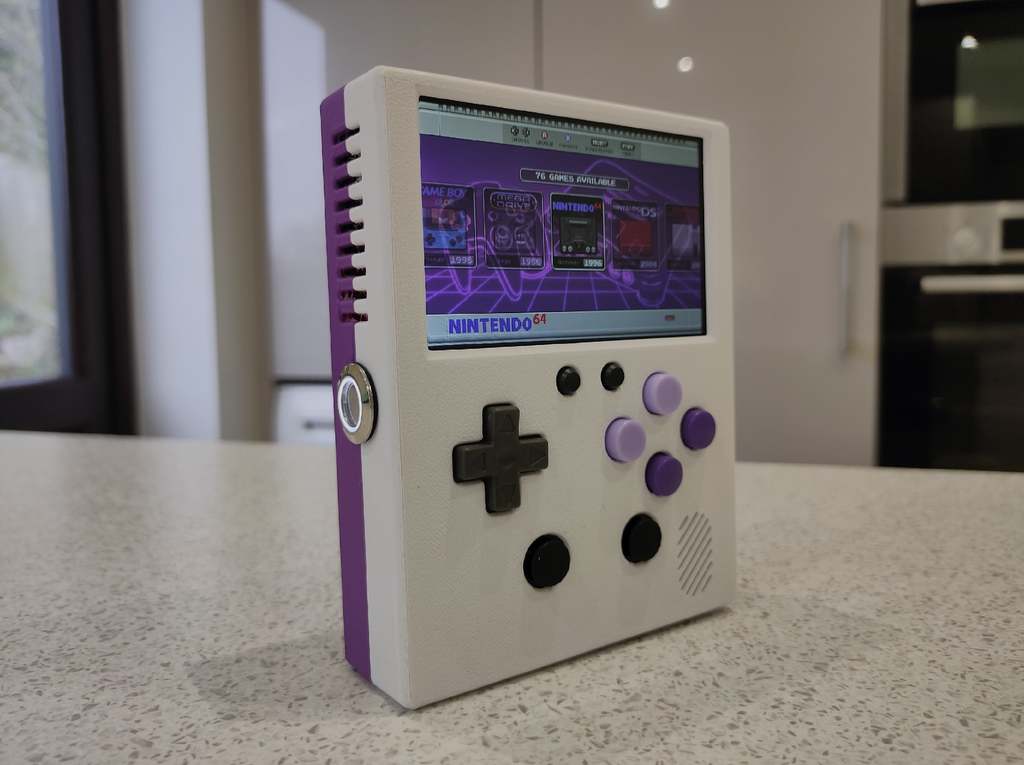
<h1>Meet the ApplePi Retro Handheld Console!</h1> *This is my first real design in a lot of ways. I've never done a full CAD design before, I've never built a handheld console before and I've never designed a circuit board before. Although this all built successfully for me, this is just a disclaimer that although I have some general background in this area I am a novice, so there is likely improvements that can be made to all areas of the design. In that regard I have also included the full STEP file, so that anyone can modify the design as they wish to fulfil their own needs or make further improvements.* **EDIT: To make the control PCB more accessible, I've uploaded the gerber files and corresponding TeensyLC controller code to PCBWAY's shared projects, so you can now simply order the PCB, and get all the required code straight from this link:** https://www.pcbway.com/project/shareproject/ApplePi_Controls_Board_7d0222d5.html <h1>1) My Design Brief</h1> After recently getting my first 3D printer and being inspired by designs across the internet (special mention to [Wermy's Gameboy Zero](https://sudomod.com/category/game-boy-zero/), and [Rasmushauschild's Super Pi Boy](https://www.thingiverse.com/thing:1779343)) I decided to design my own handheld retro console. The console is designed around a Raspberry Pi 4. Although this is a less common choice for handheld gaming consoles due to both it's high power draw and larger form factor, I wanted a console which was capable of emulating N64, PSX, PSP and NDS to a decent level of performance. After choosing main board for my console I decided to set myself a list of design requirements which would influence how my console was created. If you are looking for any of the features in the following list then the **ApplePi** might be a good choice for you. My full set of design requirements were: + Raspberry Pi 4 as the main board + 4-inch, high-quality screen (60fps, non-composite video, 480p+ resolution) + Homage to the original Gameboy DMG form factor + 4 Hour+ battery life + Mono speaker with headphone jack option + Physical volume control + Large variety of control input options (d-pad, 4 face buttons, select, start, double analogue stick, 4 "shoulder" buttons) + No tactile push buttons for the d-pad or face buttons (Rubber conductive membranes instead) + No soldering to the Raspberry Pi, all connections must use existing ports or GPIO. + USB-C charging + Device must be able to run and charge simultaneously <h1>2) The Parts</h1> This wasn't a small project and ended up requiring a quite large collection of boards, connectors, wires and screws. Some of these items can probably be changed for cheaper or better alternatives, but these are the exact elements I used: <h2>Main Components</h2> + [Raspberry Pi 4 Model B](https://thepihut.com/collections/raspberry-pi/products/raspberry-pi-4-model-b?variant=20064052740158) *(Pi Hut)* + [HyperPixel 4.0 Screen](https://shop.pimoroni.com/products/hyperpixel-4?variant=12569485443155) *(Pimoroni)* + [6700mAh LiPo Battery](https://shop.pimoroni.com/products/high-capacity-lithium-ion-battery-pack?variant=32012684591187) *(Pimoroni)* + [USB Lilon/LiPoly Charger (V1.2)](https://www.adafruit.com/product/259) *(Adafruit)* + [USB-C Breakout](https://www.sparkfun.com/products/15100) *(SparkFun)* + [PowerBoost 1000 Basic](https://www.adafruit.com/product/2030) *(Adafruit)* + [TeensyLC](https://shop.pimoroni.com/products/teensy-lc?variant=1135881265) *(Pimoroni)* + [Class D 2.5W Audio Amplifier PAM8302](https://www.adafruit.com/product/2130) *(Adafruit)* + Bespoke Control PCB *(Ordered from JLCPCB, full design in STEP file)* + [PSP Joystick x 2](https://thepihut.com/products/psp-2-axis-analog-thumb-joystick) *(Pi Hut)* + [16mm LED Push Button Switch](https://thepihut.com/products/rugged-metal-pushbutton-with-white-led-ring) *(Pi Hut)* + [Mini Oval Speaker](https://thepihut.com/products/mini-oval-speaker-8-ohm-1-watt) *(Pi Hut)* + [Rubber Tactile Button Pads](https://thepihut.com/products/black-soft-caps-for-tactile-buttons-1-pack) *(Pi Hut)* + [Tactile Switch Pack](https://thepihut.com/products/180-piece-ultimate-tactile-button-kit) *(Pi Hut)* + [Generic Headphone Jack](https://thepihut.com/products/breadboard-friendly-3-5mm-stereo-headphone-jack) *(Pi Hut)* + B103 Potentiometer Volume Wheel <h2>Wires, Screws, Extras</h2> + 26AWG Silicon Insulated Wire *(for data lines, low power connections)* + 22AWG Silicon Insulated Wire *(for high draw power connections)* + 4 x M2x4 Screws *(for PSP analogue sticks)* + 3 x M2x5 Screws *(for Charger board)* + 8 x M2.5x5 Screws *(for Control PCB and PowerBoost)* + 4 x M2.5x14 Screws *(for connecting the L1/R1 and L2/R2 buttons to their hinges)* + 3 x M2.5x25 Screws *(for Joining the case together)* + 1 x M2.5x8 Screw *(for Joining the case together)* + 2 x M3x5 Screws *(for USB-C Breakout Board)* + SNES D-Pad + SNES Face Buttons (A, B, X, Y) + SNES Rubber Conductive Membranes *(available on Ebay, AliExpress etc)* + Breakaway 0.1" Pin Headers + Unwanted/Cheap Headphones *(to cut up for the headphone jack and wires)* + Unwanted/Cheap 3A USB-C *(to cut up for connecting the PowerBoost to Raspberry Pi)* + Unwanted/Cheap USB A *(to cut up for connecting the TeensyLC to the Raspberry Pi)* <h1>3) The Build</h1> I would recommend building each section at a time and doing through testing of each element before you start combing things together. This will make troubleshooting a lot easier if something goes wrong. It helps to use a multi-meter to check connections are good and no shorts have been made before you run power through anything. <h2> Front Controls </h2> 1. Solder the headers onto the control PCB so that the standoffs are on the opposite side to the conductive pads. 2. Solder two tactile buttons onto the control PCB into the pinholes labelled ST_* and SL_*. 3. Solder the TeensyLC onto the headers. 4. Solder the 4 wires for each joystick onto the control PCB. 5. In the front case, place the analogue sticks into their housings and screw them in. 6. Position the face buttons and d-pad into their respective holes. Position the rubber membranes on top of the buttons. 7. Screw the control PCB into the front case so that it presses the rubber membranes into the buttons firmly. At this point check the feel of the buttons and adjust the tightness of the screws and position of the rubber membranes until you are happy. 8. Solder the analogue stick wires from the control PCB onto their respective analogue sticks. <h2> Power </h2> 1. **(Optional)** If you want faster charging at the expense of more heat then on the charger board, de-solder the "PROG" resistor and solder a 1.0k ohm resistor in its place (for 1A charging). 2. Solder two short 22AWG wires to the VIN and GND on the charger board. 3. Screw the charger board into the front case (the connectors and chips face toward the front). 4. Solder the VIN and GND wires from charging board to the VBUS and GND connectors on the USB-C breakout board. 5. Screw the USB-C breakout board into place. 6. Solder the JST connector onto the PowerBoost board. 7. Trim down a USB-C cable to as thin as possible (I actually removed all the plastic/rubber housing all the way down to the metal and control board, and recovered it with kafton tape when I was finished). De-solder any connected wires and solder 22AWG wires to the VIN and GND connectors. 8. Solder the trimmed USB-C cable to the PowerBoost boosted output. 9. On the push button switch solder a 26AWG wire from the C pin to a GND pinhole on the PowerBoost board. 10. On the push button switch solder a 26AWG wire from the NC pin to the - pin. 11. On the push button solder a 26AWG wire from the NC pin to the EN pinhole in the PowerBoost board. 12. On the push button switch solder a 26AWG wire from the + pin to a 5V output on the PowerBoost board. <h2> Audio </h2> 1. Cut the headphone jack and a small length of cable off an old/cheap pair of headphones. Strip and expose the wires, there should be 2 black or uninsulated ground wires, a red wire (right audio) and green wire (left audio). Combine the two ground wires and solder them together, and tin the other two wires. 2. Solder 2 mid-length wires into the boosted 5V and GND pin holes of the Powerboost. 3. Solder the other end of the GND wire from the PowerBoost with the joined ground wires from the headphone jack, and another short wire. 4. **(Optional)** To improve audio quality take a 26AWG wire and solder two small (between 10 ohm and 100ohm) resistors together with the end of the wire. 5. With the B103 potentiometer wheel facing up the pins are numbered from 1 to 5, left to right. + Solder the now combined 3 ground wires to pin 1. + Solder the green headphone jack wire to pin 2. + Solder the end of one of the resistors from step 4 to pin 3. + Solder the red headphone jack wire to pin 4. + solder the end of the other resistor from step 4 to pin 5. 6. Two wires should be left unconnected from the B103 potentiometer, a ground wire from pin 1, and the wire connected to the two resistors connected to pins 3 and 5. Take the wire from pin 1 and solder it to the A- pinhole on the amplifier board. Take the wire from pins 3 and 5 and solder it to the A+ pinhole on the amplifier board. 7. Trim the JST connector off the speaker. 8. The headphone jack has 4 pins along the back and 1 pin at the front. Solder a cable between the two inner pins. Solder another cable between the two outer pins. (As we are only using mono sound, we can just bridge these pins). 9. Solder a 26AWG wire from the + pinhole on the amplifier board to either of the outer pins on the headphone jack. 10. Solder a 26AWG wire from the - pinhole on the amplifier board to the pin at the front of the headphone jack. 11. Solder the black (ground) wire from the speaker to the pin at the front of the headphone jack. 12. Solder the red wire from the speaker to either of the inner pins of the headphone jack. <h2> Final Connections </h2> 1. Push tactical buttons into the back case centre housing so that two of the legs of each switch go through the provided holes. 2. Place the L1, L2, R1 and R2 switches into their holes (from inside the back case) and screw them in. They should hold the tactile buttons in place but not trigger them until pressed. Check the switches all work and adjust the screws and switch positions until they work as intended. 3. Each tactile switch should now have two legs visible round the outside of the housing. For each switch just see it as a "top" leg and "bottom" leg. 4. Solder the bottom legs of all 4 switches together by running 26AWG wire between them. 5. From any one of the bottom legs solder a long wire to any of the **_GND pinholes on the top of the control PCB. 6. Solder a long wire to each of the top legs and then solder the other end to the corresponding pinhole (R1+, R2+, L1+, L2+) on the control PCB. 7. Plug the headphone jack into the Raspberry Pi. 8. Plug the USB-C from the PowerBoost into the Raspberry Pi. 9. Plug a USB A to Micro USB from TeesnyLC into the Raspberry Pi. 10. Plug the PowerBoost JST connector into the LOAD port of the Charger Board. 11. Plug the Battery JST connector into the BAT port of the Charger Board. 12. Turn it on! <h1> 4) Final Points </h1> I had a lot of fun just designing and messing around with this project and I would highly encourage everyone to have a go at making their own build from scratch as it is very rewarding. If you do decided to build this project or try to improve it with your own remixes then go right ahead! I would also love to hear about and see any other variations which people manage to make. If you have any questions about the design or build then I will do my best to answer them when I can, but I won't likely be taking requests to make further changes to the design unless some major flaws are discovered. I hope you all enjoy this project, happy building and happy gaming!
With this file you will be able to print ApplePi Retro Handheld Console with your 3D printer. Click on the button and save the file on your computer to work, edit or customize your design. You can also find more 3D designs for printers on ApplePi Retro Handheld Console.