Arduino controlled Dimmer Switch
thingiverse
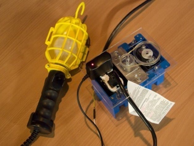
Create an outlet control with a servo and dimmer switch, featuring a 3-gang junction box, NEMA compliant components, power cord, and acrylic faceplates. Wire the outlet and dimmer to the plug, cutting and fastening the acrylic pieces accordingly. Assemble the large pulley around the servo horn with three acrylic layers and #4-40 bolts. Replace the dimmer switch nob with a smaller pulley and attach a rubber band between the two pulleys for operation. Follow Arduino playground servo tutorials to program the HS-322HD's 180-degree range, enhanced by the 2:1 pulley ratio to fully rotate the dimmer switch. See it in action at andrewparnell.com/blog/id=148.
With this file you will be able to print Arduino controlled Dimmer Switch with your 3D printer. Click on the button and save the file on your computer to work, edit or customize your design. You can also find more 3D designs for printers on Arduino controlled Dimmer Switch.