Arduino Mini Pro Holder and Wire Manager
thingiverse
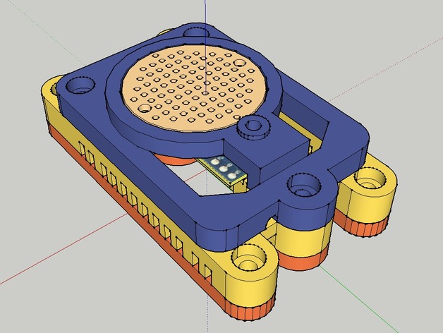
Three-piece Arduino Mini holder with multple upper assembly variation. Three upper variations inlclude a single LED holder, a triple LED holder, and a circuit board holder. Clamps the tiny board in place, and also supports it from the bottom using double sided tape (best case is to use the thinnest you can find). Cable routing notches are cut around the holder to organize the work. Assembly is intended to be attached inside an electronics box, or surface-mounted on acrylic. Point is to hold the board in place while working on it, without affecting the space needed to accomodate the bundle of wires that attach to it; to provide the ability to hold the Mini in place and organize your work as you go; and then to make it look decent when you attach it to something. Instructions Extrude the middle piece, then the upper, then the lower (refer to image for which part is which). As each part is finished, clean up with a Dremel, the occasional drill bit, or razor blade as needed. My MakerBot left a bunch of plastic strings (especially in the detail areas in the wire channels) and there is support plastic to remove. Additionally, sometimes the screw holes need to be cleaned out (on a higher resolution printer, this may not be necessary). When the middle component is complete, cut a 3/8" light velcro strip and attach it to the bar in the middle, and then to the middle of the underside of the Mini (see image). This will hold the Mini in place while retaining the option to remove it later. You can glue it instead and still have access to the solder sockets. If attaching a USB cable, bend pin inserts as shown using a vice and a tool that has a wide flat surface (e.g. a spatula). This will place the pins at 90 degrees to allow the cable to leave the mounting assembly at the desired angle. Attach the USB cable if using one, and then place the Mini on the velcro. Insert the three nuts for the M3x16mm bolts on the underside of the middle part (including 3mm head, the bolt is 19mm in total length, but is called a '16mm'). Insert M3 bolts on the upper part and screw them down only with enough pressure to hold the Mini in place (the screws will extend a bit beyond the bottom of the middle assembly to act as a "pin-guides" for the lower assembly). The design uses the velcro to provide a cushion and pressure, if your Mini is bending, it is too tight. With the upper and middle assembly in place, you can now solder wires, using the plastic structure to hold the Mini while you work (see image). Organize, and route wires as required in the cable channels. When wires are in place, flip over assembly, ensure the wires are in the desired channels, and attach lower part using two small screws (not bolts). I had to retap the screw holes with a small drill bit to ensure the screws had somewhere to go. Four remaining screw holes are for mounting to a surface or project box (A 1 1/2" x 2 7/16" x 4 3/8" project box was used in this case - mounting holes can be moved in SketchUp with a bit of effort). Again, Velcro or glue can also be used in place of mounting screws. Included in the design is a tube for the reset button and a mount for a 5mm LED that you can attach to pin 13 without requiring a resistor. Both of these can be removed if they are not wanted. You will need to adjust LED indicator and reset tube (sand or cut) to mate with box lid. The intent is to modify the height of each of these as required such that you can reset the Mini or view board activity from the outside without being forced to open the case. Next version will incorporate a battery box and a place to include a commercial electronics board of average size.
With this file you will be able to print Arduino Mini Pro Holder and Wire Manager with your 3D printer. Click on the button and save the file on your computer to work, edit or customize your design. You can also find more 3D designs for printers on Arduino Mini Pro Holder and Wire Manager.