ATMega8 ATMega328P Voltmeter PCB
thingiverse
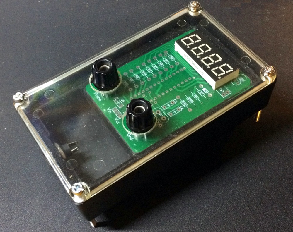
This thing is about my own pcb used for building a simple 3 digit LED DVM. It runs the meter based on ATMega8-PU and ATMega328P. Update: Now we have even more holes but no leakage - the acrylic cover. Made an insert holding the pcb tightly. See the new pics. This printable part had to fit a particular unnamed extremly low quality peace of junk. It might not be available on all places. Better stay away from it. Seriously. Sorry but the first bought Hammond case did not make a fit. Could try another one later on. A slightly patched pcb runs a 5 digit RPM-counter. Link to the project sw files below. It makes use of a small 4 digit 0.39 inch LED display (LFD039BAG-102) The least significant digit of course is not visible on a 4 digit LED display. How to patch the pcb traces in order to make it a rpm-meter Picture showing how to reassign a few signals in order to -make fetching external events by triggering Int0 and Int1 accessible. -Extend the display to 4 digits. Attach the 4th digit to the former HOLD-LED pin or choose another unused i.e. PB5. In order to use the 4 digit display the tactile switch and the Hold-LED have to go or to be moved to the back side. Hint: Put on a 2 pin JST-HX connector instead of the lousy, weak thin wires connecting the battery clip. Increase the display brighness by adding a little delay when it switches the segments on. I found a delay(1) = 1milli second is long enough. It might not be suffeciently bright enough to work outside even in the sun light. But inside my workshop it is look ok. Of course the change increased the power consumption a bit. Now it draws a current of 37mA when all segments are lit up. If You do not have a 16MHz crystal on hand, choose the proper MCU supported by Arduino IDE board definitions . Adjust the compiler settings this way. If in doubt set the fuses manually afterwards matching a newly generated hex-file. It runs at 8Mhz from the internal RC-oscillator with no problem regarding the frequencies, conversion rate, refresh rate, delay, millis, etc. If using the Hammond 1951XXL case it needs to be modified a lot. Most important the cuts on the standoffs. The edge of the slots (moreover the one going closer to the top of the case) are showing a possible position, depending on how far the pcb should dive in. Tricky but doable. The LED display needs to be leveled up a bit. When using the cut out it should not sit flush on the pcb. The pcb design I made has been "inspired" by something sold by Venator expensive too much (dearly). Politely spoken! When I started making the disign only a few incomplete/much distorted pictures could be found. Now having finished my first build I have access to an original pcb. Made high res plain pictures. For reading even the covered traces I have removed the silkscreen from the back. The original maker refuses to publish the files that would allow to make the pcb easily. Had asked him for plain pdf-files. But NO, he denied. Stupid. Using the meter. PLS take care, it is for positive polarity DC voltage only. No overvoltage protection built in. The meter circuit deserves a filtering circuit on the power input and a low pass filter on the measuring input as well According to the original makers description the voltagedevider consisting of R12,R13 allows up to 100volt DC on the input. This can be changed easily. Read the linked sources. It does not indicate when a negative polarity signal has been put on the measuring input terminal Minimum changes I do on my meter builds. Add to or replace (slightly different parts numbering) -C3 by an electrolytic capacitor 10uF/10volts , between R12 and Q1 -C4 by an electrolytic capacitor 10uF/10volts , between R12 and Q1 -C6 by a tantulum capacitor 100/220uF/25volts. next to Vin Take care on the orientation. Put the negative leads of the caps to the ground trace. It helps a lot reducing the flickering when reading voltage from a regulated psu that caused much flickering before. No longer a big problem when powering from external PSU that caused much flickering before. Now the flickering issue has almost gone after adding the capacitors. Still present when the input voltage toggles a digit on the display from one number to the next number (back and forward). Software related, calculating the average of many samples, rounding the result. PLS take note: Not all of the 3 digit pins are conected to PWM outputs. Just like so: Dig1-3 ---> function D10,11,12 ---> Pin 16,17,18 The PWM pins on the ATMega328 chip are 11,12,15,16,17. Writing your own code on the Arduino IDE the sevenseg-library (Sparkfun, Nathan Seidle) can not be utilized. This handy library depends on using PWM. Minimum code changes: The visual appearance of the number "9" on the display looks very bad . It does not show the segment "d". Solution: change the code a bit if (y == 9){ digitalWrite(a, LOW); digitalWrite(b, LOW); digitalWrite(c, LOW); digitalWrite(d, HIGH); <----change here to LOW digitalWrite(e, HIGH); digitalWrite(f, LOW); digitalWrite(g, LOW); And a few lines below if (y == 9){ digitalWrite(a, HIGH); digitalWrite(b, HIGH); digitalWrite(c, HIGH); digitalWrite(d, LOW); <--- change to HIGH digitalWrite(e, LOW); digitalWrite(f, HIGH); digitalWrite(g, HIGH); Set the fuses by Arduino IDE automatically or manually when using an external programmer. Fuse settings for the 16MHz quartz resonator. low byte: 0xFF high byte: 0xDA (0xDE) extended:0xFD lock bit byte: 0xFF (have not set any locks) LED displays: I'm using the CA LED display Wenrun LTD040BAG-101 (green). Some LED displays (3 digit, common anode, 0.4 inch, row pitch of 12.7mm) -Wenrun 12.7mm LTD040BUE-101A red CA -Wenrun 12.7mm LTD040BAG-101 green CA -SunLED 12.7mm DUY10A3-A yellow CA -SunLED 12.7mm DUG10A3 green CA -Luckylight 12.7mm KW3-401AVA green CA -Luckylight 12.7mm KW3-401AGA red CA -LiteOn 12.7mm LED LTC-46C5S 20150827 The files: (single sided and double sided layout) The stl file has the 3D model of the populated pcb when using terminal post with 16mm wide caps. Latest release V1033, changed for more common tactile switch New design: the single sided pcb (Sprint Layout6) Rev 135, Rev 136 Requires a few wire bridges. Have stopped further development on the single sided pcb. The pcb file size is 51x75mm now. All the drawings are NOT mirrored, all view from top side. Build instructions: For the (original) kit build instructions http://www.venatormfg.com/voltmeter-section-4-assembling-the-voltmeter.html When using CC LED displays change the code as needed, read the source code I have used slightly different parts numbering on my pcb silk screen. Experience "using" the built meters. Do not trust the manufacturer of the parts. Even if they have been sold from reputable source 0.1% perenct accuracy might not fit the bill. The linked sources have an number of valuable instrucutions how to make it a decently good working measuring device. Literatur: -Filtering routine (does not work ok) https://tttapa.github.io/Arduino-Filters/Doxygen/d3/dbe/1_8FilteredAnalog_8ino-example.html -Precise mearuring using external reference sources https://42project.net/praezise-analoge-spannungsmessungen-mit-dem-arduino-anhand-einer-referenzspannung-messen/ -Fast sampling a signal http://yaab-arduino.blogspot.com/2015/02/fast-sampling-from-analog-input.html -Make more precise reading https://stackoverflow.com/questions/56316211/how-to-make-more-precise-the-reading-of-analogpins-in-arduino -Filtering a noisy input signal https://42project.net/drei-methoden-zur-filterung-von-verrauschten-adc-messungen-mit-dem-arduino/ -Continuity tester using sleep mode in order to save energy http://www.technoblogy.com/show?1YON -Similar auto range voltmeter, BASCOM code, first published 2013 https://www.elektronik-labor.de/AVR/dds/DVM.html -LM4040 circuitry (with voltage devider) resistor calculation https://webcache.googleusercontent.com/search?q=cache:fFH1SJUb_MgJ:https://forums.adafruit.com/viewtopic.php%3Ff%3D19%26t%3D62492 -Präzise Spannungsmessung mit dem Arduino https://elektro.turanis.de/html/prj130/index.html Do "analogReference(EXTERNAL)" before "analogRead()" -Arduino-Programmierung Analogeingang http://www.netzmafia.de/skripten/hardware/Arduino/Programmierung/arduino-analog.html From the Arduino IDE hardware definition file ## Arduino Uno w/ ATmega328 16Mhz uno.menu.cpu.atmega32816=ATmega328 16Mhz uno.menu.cpu.atmega32816.upload.maximum_size=32256 uno.menu.cpu.atmega32816.upload.maximum_data_size=2048 uno.menu.cpu.atmega32816.upload.speed=115200 uno.menu.cpu.atmega32816.bootloader.high_fuses=0xDE uno.menu.cpu.atmega32816.bootloader.low_fuses=0xFF uno.menu.cpu.atmega32816.bootloader.extended_fuses=0x05 uno.menu.cpu.atmega32816.bootloader.lock_bits=0x0F uno.menu.cpu.atmega32816.bootloader.unlock_bits=0x3F uno.menu.cpu.atmega32816.bootloader.file=optiboot/optiboot_atmega328.hex uno.menu.cpu.atmega32816.build.mcu=atmega328p uno.menu.cpu.atmega32816.build.f_cpu=16000000L -https://www.changpuak.ch/electronics/LED-DigitalVoltmeterModule.php See the ATMega8 DVM schematics PDF-file Similar Mini 4-digit DVM based on ATMega8. It has explained the code in every possible detail (russian language) -https://radiokot.ru/circuit/digital/measure/109/ The maker has shared all the files and the code on PCBWAY -https://www.pcbway.com/project/shareproject/___________________5172.html -http://www.netzmafia.de/skripten/hardware/Arduino/Programmierung/ADC-Eingang.gif Driving LED with no resistors, just PWM output -https://github.com/tehniq3/multiplexedclock4/blob/master/multiplexedclock4_3.ino based on a sketch for multiplexed display: 6-13-2011, Spark Fun Electronics 2011, Nathan Seidle https://github.com/tehniq3/multiplexedclock4/blob/master/multiplexedclock4_3.ino https://github.com/tehniq3/thermostat/blob/master/thermostat.ino -simple cnc spindle rpm counter http://samopal.pro/cnc-new-3/
With this file you will be able to print ATMega8 ATMega328P Voltmeter PCB with your 3D printer. Click on the button and save the file on your computer to work, edit or customize your design. You can also find more 3D designs for printers on ATMega8 ATMega328P Voltmeter PCB.