Automatic Iris Mechanism
thingiverse
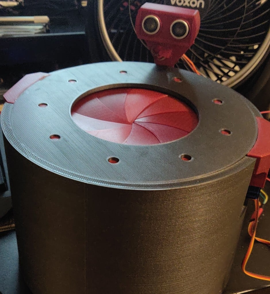
As the original didn't leave instructions, I decided it would be fun to try and figure out how it worked and ended up editing almost all the different elements and adding some more to it as well so it turned into a remix. What you need: - Cyanoacrylate Glue - Screwdriver - 2 x SG90 Servos - 1 x HC-SR04 - 1 x Arduino Uno - 1 x Breadboard/Mini-Breadboard - Many Dupont Wires (Like these:- https://www.amazon.co.uk/Elegoo-120pcs-Multicolored-Breadboard-arduino-colorful/dp/B01EV70C78/) Method: If you have Blender, open this file to get an idea of what it'll turn out like when it's built. (Only for the build reference) - full_model.blend Print: - 1 x Iris_holder.stl - 9 x Iris_leaf_pin.stl - 9 x Iris_leaf.stl Each leaf has been marked with a little circle indent, this marks where to glue the leaf pin, I glued it on as it makes the leaves easier to print without supports, as supports would leave marks that would make the surface rougher so it wouldn't spin as easily. Place the leaves in the iris holder, circling the edge, one overlapping the next. Print: - 1 x Iris_spin_mechanism.stl - 1 x Iris_bottom_cover.stl - 2 x Iris_spinner_pin.stl Place the spin mechanism, over the small pins of the leaves, the flat side of the spin mechanism facing away from the pins, so that the curved inner edge of the spinner is facing the leaves, this helps guide the leaves back in. (I suggest sanding the curved inner edge so it's smoother and the leaves don't catch on the layers) Gently turn the spinner plate to check it closes and opens the iris. Place the cover over the top, line up the two holes so that there is one on the left and one on the right (relative to you as it's circular). Attach the spinner pins to the spin plate, lined up with the holes in the cover so that when you move them along the holes in the cover the spin plate will open and close the iris, then glue down the tabs of the cover to the side of the iris holder. Reference the pictures if my description is nonsense. Print: - 2 x Servo_side_holder.stl - 2 x Servo_arm_2.stl - 1 x Ultrasonic_holder.stl - 1 x Ultrasonic_case_lid.stl Wire the ultrasonic sensor and servos to the Arduino as shown in the wiring diagram. Connect the Arduino to PC. Run this code, if connected correctly, when you wave a hand near the ultrasonic sensor the servos should activate. // Code Start \#include <Servo.h\> Servo servo_1; Servo servo_2; int pos = 100; const int EchoPin = 4; const int TriggerPin = 6; const int servo_1_pin = 9; const int servo_2_pin = 7; bool opened = false; const int trigger_distance = 15; const int close_point = 85; const int open_point = 150; void setup() { Serial.begin(9600); servo_1.attach(servo_1_pin); servo_2.attach(servo_2_pin); pinMode(TriggerPin, OUTPUT); pinMode(EchoPin, INPUT); } void loop() { int cm = ping(TriggerPin, EchoPin); Serial.print("Distance: "); Serial.println(cm); delay(50); } int ping(int TriggerPin, int EchoPin) { long duration, distanceCm; digitalWrite(TriggerPin, HIGH); delayMicroseconds(10); digitalWrite(TriggerPin, LOW); duration = pulseIn(EchoPin, HIGH); distanceCm = duration * 10 / 292 / 2; if (distanceCm <= trigger_distance && opened == false) { open(); } else if (distanceCm >= trigger_distance && opened == true) { close(); } return distanceCm; } void close() { for (pos = open_point; pos >= close_point; pos -= 2) { servo_1.write(pos); servo_2.write(pos); } opened = false; delay(350); } void open() { for (pos = close_point; pos <= open_point; pos += 2) { servo_1.write(pos); servo_2.write(pos); } opened = true; delay(350); } // Code End Line up the two Servos and attach the arms at roughly a 40-degree angle from the short side of the servo. Screw them in (when you've tested it, add a dab of glue to make sure it stays strong). Run the code, the servo arms should move about 90-degrees along the long side of the servo. Attach the servos to the side servo holders, then put the arm...holes over the spinner pins and glue the holders to the side of the iris holder. Put the Ultrasonic sensor in the case and glue it to the base, check the pictures again for reference. Change these numbers in the code and reupload it to adjust the open and close positions. const int close_point = 85; const int open_point = 150; That's it, enjoy.
With this file you will be able to print Automatic Iris Mechanism with your 3D printer. Click on the button and save the file on your computer to work, edit or customize your design. You can also find more 3D designs for printers on Automatic Iris Mechanism.