Automatic Plant watering system -ultra cheap v2
thingiverse
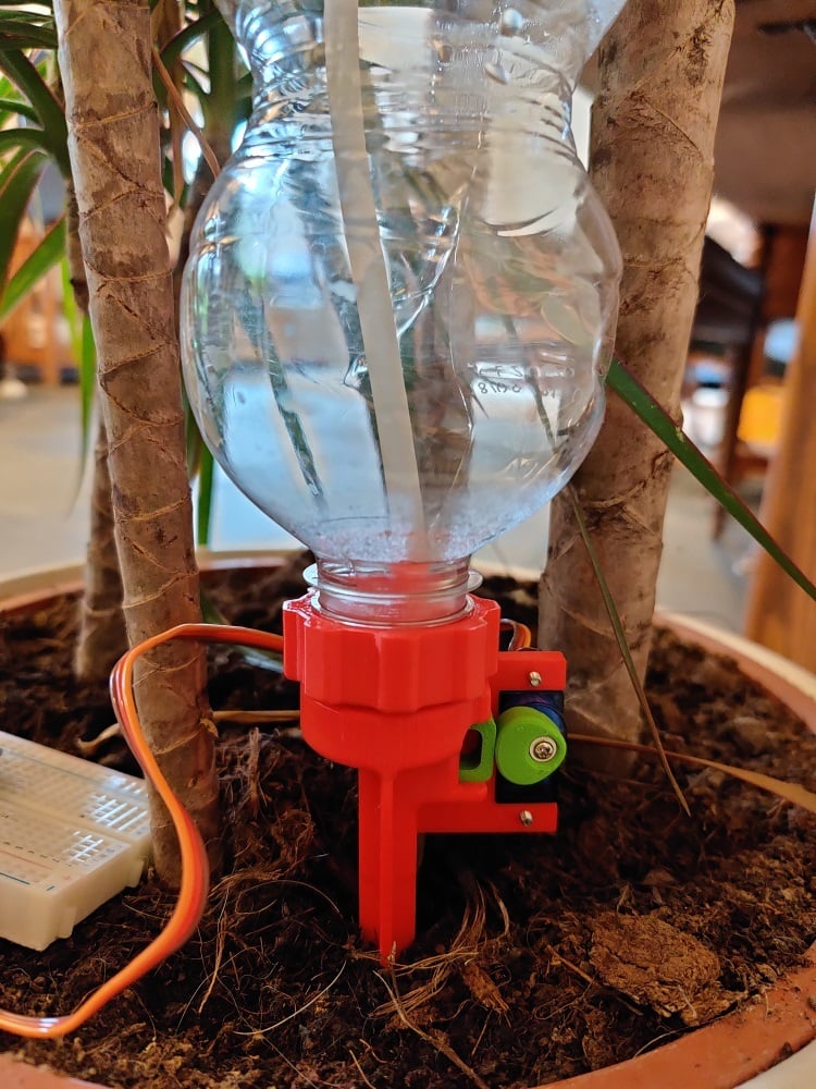
Work in progress: 27 December 2020 Updates -almost complete redesign to add a vent to the water bottle. This vent also required improved seals to the water bottle to prevent leaks. I left the 'old' versions of the files. If you want the most recent revision, print the later revision parts. The new 'seal test' part should be printed in TPU, TPE or similar soft compliant material. You must use a hard enough durometer to allow hose connections to the barbs, however. The vent line is the same size silicone aquarium hose as used for the water supply to the plant. This line should be long enough to reach the top of the water bottle. When assembling, first put the 'pass through' part into the nut, then press the 'seal test' part into the nut. This fit will require some manipulation to snap it in place. The pass through is designed for a 1/4 turn twist lock connection into the valve body. I wanted to design the cheapest possible automatic plant watering system. You should be able to make this from things you have around the house plus less than $10 worth of parts. Instructions This design only requires a few purchased components: -arduino or raspberry pi (I used a Arduino nano clone) -9g RC servo (I used a plastic gear 9g tower pro SG90) -silicone fish tank air hose, 6mm OD / 4mm ID -two M2 or 2/56 screws to attach RC servo to device -20 ounce or 500mL soda / water bottle This watering system uses a simple pinch mechanism as a valve to control water flow. The servo turns a cam, which moves a cam follower and pinches the silicone hose. The cam follower was originally intended to be printed from TPU, but it turns out PLA worked just fine. I thought a flexible cam follower would reduce the risk of the servo stalling, but it doesn't seem to be necessary. A sample arduino sketch is included- you'll want to play with this to set timing where you need it for your particular plant. The sketch attempts to reduce power consumption by disconnecting the servo when the system is in the valve closed state. The arduino is connected to the servo via Vin, ground, and pin 9 (changeable in the sketch). I powered the arduino with a block of 4 AA rechargable batteries connected to Vin and ground. An improved version would completely cut the power to the servo during wait periods instead of just disconnecting the control. This would certainly improve battery life. I wasn't succesfully able to run this from a USB power bank, as it didn't draw enough current and the power bank shut off. It does work fine from a USB power adapter. When you assemble the system, you'll want to carefully set the servo up so that 0 degrees on the servo corresponds to the valve fully closed. The cam is designed so the servo isn't under any load when the valve is closed. You can do this by wiring the arduino to the servo, then running a sample sketch to move the servo to 0 degrees, then cutting power to the servo. Then you can carefully assemble the watering system. Solidworks 2017 files are included for your remixing fun. I didn't include the servo model as this was another person's work, so this will cause the assembly drawing to fail. When I have time I'll probably design an improved version with a nice case for the arduino & battery supply, plus improved power management.
With this file you will be able to print Automatic Plant watering system -ultra cheap v2 with your 3D printer. Click on the button and save the file on your computer to work, edit or customize your design. You can also find more 3D designs for printers on Automatic Plant watering system -ultra cheap v2.