Back to the Future Time circuit Delorean replica prop
thingiverse
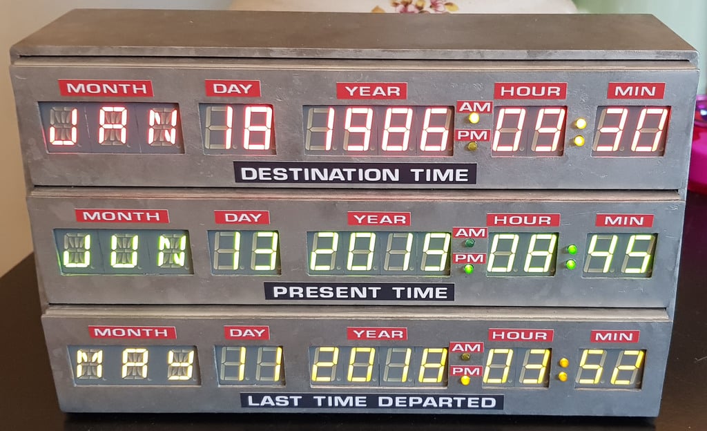
Replica of the Delorean time circuit of "Back to the future" MAJ : 12 aout 2019 PRINT: The object consists of 8 pieces to print with a layer height of 0.2mm and a line width of 0.4mm: - Capot (print = 2h00, no supports). - Futur red module (print = 4h20, no supports). - Présent green module (print = 4h20, no supports). - Past yellow module (print = 4h20, no supports). - Rebord Left ( print =2h00, with support) - Rebord Right (print = 2h00, with support) - 2 reinforcement bar on the back (print=2h00, with support) PROGRAMMING: -the arduino code works very well (see the video). This is the exact replica of the movie clock. -You can change the date in the future and in the past very simply. -The present date synchronizes with your computer. -The LED change for the AM / PM is automatic. -BUT ... it's a very complex programming (bit by bit). I could not help you debug if you want to change something. INSCRIPTION ON THE FRONT SIDE: I searched for the most accurate typography. PDF to print MATÉRIALS: - 9 X Alphanumeric Display 16 segments 25 x 16mm (3 reds, 3 greens and 3 yellows). There are many manufacturers like for example: https://www.kingbrightusa.com - 30 X Numeric Display 7 segments 19,05 X 12,7mm (10 R, 10 G and 10 Y). - 3 X identical Printed Circuit Boards (PCB) (*). - 3 X Adafruit 16x8 LED Matrix Driver Backpack - HT16K33 Breakout https://www.adafruit.com/product/1427 - 1 X Arduino Nano or equivalent https://store.arduino.cc/arduino-nano - 1 X Breadboard-friendly SPDT Slide Switch https://www.adafruit.com/product/805 - 1 X Adafruit DS3231 Precision RTC Breakout if you want to display today's date. (I gave up the DS1307 module because it had too much time drift). https://www.adafruit.com/product/3013) - 1 x USB Micro-B Breakout Board (the same as on the arduino nano) that will serve as a power switch because arduino nano is not made to power 360 LEDs! https://www.adafruit.com/product/1833 - 8 X LED 3mm yellow - 4 X LED 3mm green - 12 X Through-Hole Resistors, 220 (for yellow) and 470(for green) ohm - 12 X screw nut M3 - Silicone cover stranded-Core Wire - 30AWG or 28AWG in Various Colors. Too rigid wires (24 or 26AWG) are a problem for positioning the displays. https://www.adafruit.com/product/2051 PRINCIPLE Check the datasheet of your displays, the order of the pins may vary depending on the manufacturer. The principle remains the same, "connect the letter of your segment (a, b, c etc ...) to the letter written on the PCB" as in the example photo. For all displays: The DP pin (the bottom right corner of all displays) is never used you can delete it. For digital displays only: there are 2 out GND (on my picture example it is pin 3 and 8). You only need one, you can delete the other. I printed a handy welding aid to check the lengths and I put the image of my templates to help you cut the cables to the right length. (*) I made a PCB to make things easier. For the manufacturing it is very simple: - Go to the website: https://jlcpcb.com/quote - Place the compressed file Gerber2.zip - The basic options are sufficient so do not change anything. - You just have to order 5 identical PCB (you will only need 3 but ...) ! https://www.youtube.com/watch?v=DiMKIziY6XQ&feature=youtu.be
With this file you will be able to print Back to the Future Time circuit Delorean replica prop with your 3D printer. Click on the button and save the file on your computer to work, edit or customize your design. You can also find more 3D designs for printers on Back to the Future Time circuit Delorean replica prop.