Balancing robot with etched PCB shield
thingiverse
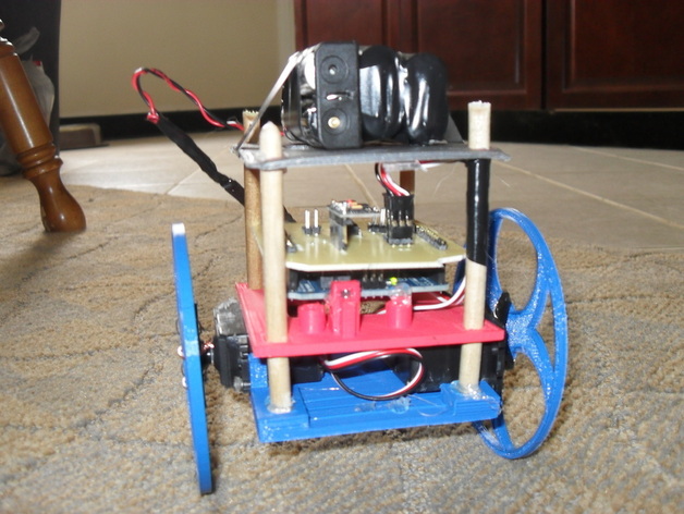
A balancing robot, equipped with printed wheels and structural components, utilizes an Arduino Uno, accelerometer/gyroscope, and a custom-made motor/servo PCB shield. Check out this bot in action via [this YouTube link](http://www.youtube.com/watch?v=LAWjUlzAYf0&feature=plcp). The robot's design has evolved from its initial prototype, which you can trace through this website: www.jddorweiler.appspot.com/electronics.html#robot. The maker aimed to create a budget-friendly balancing robot using affordable, common components instead of expensive electronics and motors. The PCB was designed using Fritzing (http://fritzing.org/) and the code can be found at http://github.com/jdorweiler/BalancingRobot. This project requires an Arduino Uno, four continuous rotation servos, an accelerometer/gyroscope board, a 5/16 or 8mm round wooden rod, and printed parts for the robot's body and wheels. Assembly is straightforward, with the wooden rods fitting snugly through the square holes in the printed parts, and thin wire used to attach the wheels to the servos. Balancing the robot may require adjustments to the parameters in the Arduino sketch, which can be tweaked for optimal performance.
With this file you will be able to print Balancing robot with etched PCB shield with your 3D printer. Click on the button and save the file on your computer to work, edit or customize your design. You can also find more 3D designs for printers on Balancing robot with etched PCB shield.