Barebones ATX PSU
thingiverse
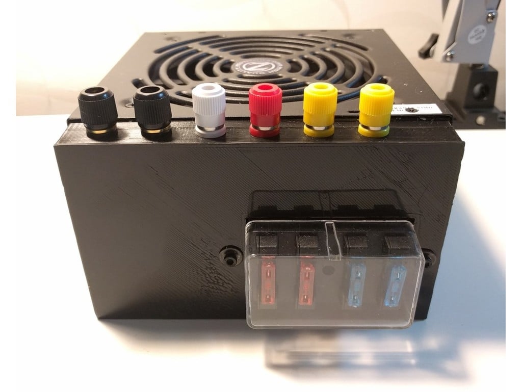
My pretty version of an ATX PSU to lab bench power supply. Follow the RepRap ATX to power supply (PSU) conversion guide for directions and warnings. There seem to be enough PSU conversion cases/fittings here so why did I upload mine: 1.) I like simplicity so no lights and a clean mounting surface. 2.) None that I saw added what I feel is vital and that is an easy to check fuse system on the PSU. 3.) These are for my kids which like to see sparks and burn things up… I like to fuse the PSU under what each power rail is rated so the fuse blows before the box smokes… The parts I used were banana posts that you can find in any electronic components store. A mini fuse box for an ATV was used for that clean easy to inspect fuse box look. The two screws run through the case and the fuse box to attach the entire assembly. The ATX PSU I buy have to have a large fan and a physical power switch. (1 less thing to buy and wire) Unfortunately every ATV fuse box I have purchased is slightly different so this would be best used as a reference part. (The ATV fuse box I used is not listed anymore on Amazon, I attached a picture what I found that was similar) UPDATE 9/9/2017: I had to make another PSU (and the box I could find was different again) and while doing that I thought I would learn about making a parametric model in FreeCAD that can survive some wild variable changes (See MKII FreeCAD file). The FreeCAD model has a spreadsheet with the parameters to fit any fuse box. (See attached picture for parameter names) It is also a good representation on how to make clean models that won’t break with parameter changes that drastically change the model because it uses Boolean operations that are relational to a geometric loft and not tied to model state. I use the word loft here liberally because in this model it’s just a square blue box set to variable a and b… (FreeCAD blue lines in sketcher are reference geometry) Old walk through for CAD continues below END UPDATE 9/9/2017 Steps for making this in CAD Directions (x = horizontal, y = vertical, Z =towards the PSU) 1.) Sketch a rectangle the size of the PSU Side and extrude (pad) to depth (mine was 20mm) (XY plane +Z extrusion) 2.) Sketch a rectangle on the Z+ surface of the extruded rectangle on step 1 (XY plane with –Z cut) a. The rectangle size should be centered with a (width – 2*thickness, height – 2* thickness) b. Cut (pocket) the rectangle into the pad in step 1 to (depth – thickness) c. Note: I used 2mm for my thickness 3.) Sketch the location of the window into your box for the fuses with a cut through all (XY plane) a. This is dependent on your fuse box 4.) Sketch the padups for the fuse box tabs (Internal face of cover +Z extrusion a. Again dependent on your fuse box (extrude = depth – thickness of the fuse box tabs) b. Make sure there is room to get your wires around your pad ups (My design was a little too tight sometimes 5.) Sketch the mounting holes for your fuse box a. Again dependent on your fuse box 6.) Add the holes for the banana posts on the +Y surface (ZX plane) a. I make mine r=4.1mm that way I don’t have to worry about drilling them out and they are loose tolerance hole and most posts are slightly oversized. b. I do not usually make the posts have the standard 19.05mm (3/4”) spacing between holes for dual plugs. I force single plugs since I don’t want one of my kids bridging different voltage lines. (I only made it 1mm different to mess with them though.. >:D ) 7.) I used automotive wire terminals to connect everything. (Blade ends at the fuse box and circle ends at the posts) 8.) To mount it match drill using the fitting into the side of the psu and run two machine screws with a nut. (Bonus points if you use Loctite or a lock nut on the nut.)
With this file you will be able to print Barebones ATX PSU with your 3D printer. Click on the button and save the file on your computer to work, edit or customize your design. You can also find more 3D designs for printers on Barebones ATX PSU.