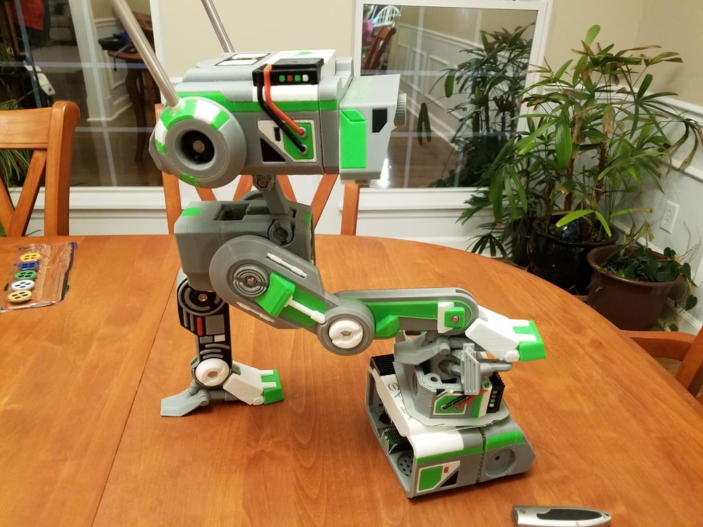
BD-1R Droid (70% Remix + MMU & 13DOF)
thingiverse
This appears to be a list of 3D printing files for a robotic head project, specifically a mechanical brain and skull structure. The files are organized by part number (e.g., Parts9, Parts10, etc.) and version (e.g., v1, v2). Each file has several variants (.stl) with different suffixes indicating the print bed orientation or color. Here's a brief summary of each section: * **Parts 9**: Torso Rear, which requires supports for the nuts and huge overhang. * **Parts 10**: Light Grids for v1 and v2 heads, with no nuts required. * **Parts 11**: Torso Front, which did not require supports despite some sagging in the middle. * **Parts 12**: Skulls (v1 and v2) with different designs and features, such as a larger light grid for v2. * **Parts 13**: DELETED (no information available) * Parts 13 v2: Many updates, including nuts, motorized head parts, tools, and a carriage for the projector assembly. Note that not all parts are necessary or recommended. * **Parts 14** and **Parts 15**: Not required for the model and may be posted later as separate things. * **Parts 16**: Another part of the face using different colors and two-tone nuts. * **Parts 17**: Projector eye part, which is likely to be noticed due to its unique design. * **Parts 18**: Cogs with varying heights, recommended to print the shortest one and trim the post if necessary. This list provides a comprehensive collection of 3D printing files for a robotic head project.
With this file you will be able to print BD-1R Droid (70% Remix + MMU & 13DOF) with your 3D printer. Click on the button and save the file on your computer to work, edit or customize your design. You can also find more 3D designs for printers on BD-1R Droid (70% Remix + MMU & 13DOF).