Bed Level Correction process
thingiverse
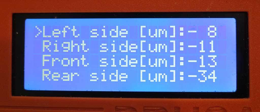
Work-in-progress... would be delighted to incorporate suggestions for improvement. Please comment or message me. * 2019-09-11 @wabbitguy suggested connecting the patches to make it easier to keep straight which is which while measuring. Was such a great idea, I had the .scad file updated almost before he sent me a picture. Also added an option to overlay an "X" and "Y" on the connections near the bottom-left origin patch. However, when I first tried to print it, the adhesion on those long skinny lines just didn't hold and made a mess. So I've included a new FirstLayerConnected.ini print settings file which turns perimeters back on but prints them after the infill. * 2019-07-20 Modified version will *not* recommend changes to live-adjust-Z but warns if patches are >125% of nominal. Removed obsolete g-code. Added center patch only. Added 1stLayerCalibrationPatches.ini print settings for PrusaSlicer 2.0.0 When I got my Prusa i3 MK2s up and running, I was intrigued by the "Bed Level Correction" settings. The [provided instructions](https://help.prusa3d.com/l/en/article/TPGip0OmaP-bed-level-correction-kit-only) are minimal, but they got me started. I suspect that other printers with a similar firmware could use this process. You must complete the basic first layer calibration before attempting this process. I like to print only the center patch repeatedly to find the live-adjust Z value that results in the *thinnest* layer, typically around 0.22mm - 0.23mm when asking for a 0.2mm first layer. If the nozzle is too high, the layer will be too thick as the extrusion isn't fully meeting its neighbors; if it is too low, the nozzle will push into adjacent layers and cause ridges to rise up past the nozzle. Both of those conditions are to be avoided. It would also be prudent if you have calibrated your extruder; I'm sure that under- or over-extrusion will affect the thickness of the first layer, and that's what you're going to be measuring. You will need a micrometer or caliper for measuring the patches. 1. Create the test patches .stl file using the Customizer. Or, if your printer bed is 250mm by 210mm and you want to test a 0.2mm layer height, you can just download the included file. Tip: Let the patches cool before removing them from the build plate and measuring!
With this file you will be able to print Bed Level Correction process with your 3D printer. Click on the button and save the file on your computer to work, edit or customize your design. You can also find more 3D designs for printers on Bed Level Correction process.
