Belt Driven CR-10 Dual Z using a single stepper motor
thingiverse
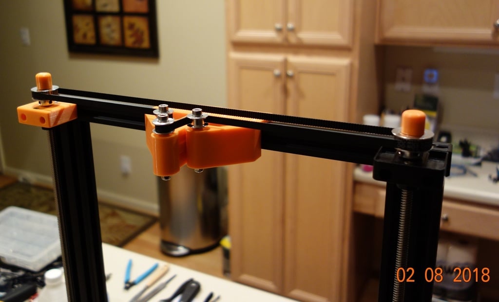
Congratulations on completing your Dual Z - one stepper mod! Here's a summary of the steps you took: 1. Installed two small screws to secure the bottom flange bearing cover. 2. Installed the top flange bearing and cover, ensuring proper alignment with the frame. 3. Adjusted the height of the second screw rod to match the first one, securing it in place with two small flat head screws. 4. Installed the 40-tooth pulleys on both Z screw rods and the middle pulley parts and belt, making sure all pulleys are at the same height. 5. Tightened the M5x50mm bolts on the side and center sliding parts, using nylon lock nuts and washers for secure installation. 6. Installed the "T" nuts in the top cross piece, securing the side pieces with M5x10mm screws. 7. Slid the center sliding part into place, installing the bottom hole's "T" nut after dropping it into the channel. 8. Installed the 852mm timing belt, tightening the top and bottom screws to secure it in place. 9. Placed the 8mm end caps on top of each Z screw rod (if desired). 10. Double-checked everything for proper alignment and tightened any loose screws. 11. Removed the supports under the X axis and manually moved the Z axis up and down, checking for binding or problems. 12. Used the "Auto Home" function to perform a final check. Your printer should now be ready to use with the Dual Z - one stepper mod!
With this file you will be able to print Belt Driven CR-10 Dual Z using a single stepper motor with your 3D printer. Click on the button and save the file on your computer to work, edit or customize your design. You can also find more 3D designs for printers on Belt Driven CR-10 Dual Z using a single stepper motor.