Belt Sander Using Drill with Foot Pedal - UPDATED
thingiverse
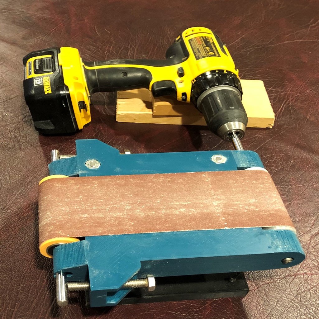
https://youtu.be/syHcDUk5NpA ******* UPDATED ***************** Added flange on idle roller to improve belt tracking ************************************** PARTS Belt Sander • Sanding Belt 3”x18” – Qty.1 • 5/16 -18 hex nut – Qty 4 • 5/16-18 x 2” Hex head screw - Qty.2 • 5/16-18 x 3” Partial Threaded Socket Head Cap Screw – Qty.2 • 608 RS Skate Bearings - Qty 4 https://www.amazon.com/gp/product/B0190LYNRK/ref=ppx_yo_dt_b_search_asin_title?ie=UTF8&psc=1 • 8mm Rods • https://www.amazon.com/gp/product/B01LXAZCE6/ref=ppx_yo_dt_b_search_asin_title?ie=UTF8&psc=1 Drive Roller • M4 x 8 socket head cap screw x 8mm • M4 square nut – Qty.2 Pedal • Cable, Cable Housing and Housing Ferrules – Qty.1 kit https://www.amazon.com/corki-Universal-Bicycle-Shifter-Derailleur/dp/B07JLWSF82/ref=sr_1_6?keywords=road+bike+shifter+cables&qid=1568334637&s=sporting-goods&sr=1-6 • ¼-20 x 1-1/4” Hex head screw – Qty.2 • ¼ -20 nylock hex nut – Qty.2 • 5/16–18 x 2-1/2” Hex head screw – Qty.1 • 5/16-18 hex nut – Qty. 1 Trigger • M4 x 30 socket head cap screw x 30mm – Qty.2 • M4 hex nut – Qty.2 ASSEMBLY INSTRUCTIONS • Press two of the 5/16” hex nuts into the hex recesses on the top of the sander body • Assemble sander body to sander base and run the two 5/16”-18 x 3” socket head cap screws through the bottom of the base and into the two hex nuts in the top of body • Press two of the 5/16” hex nuts into the side arms of the sander body • Thread the two 5/16”-18 x 2” screws through the back of the body and into the hex nuts just past the nut (these are the idle roller jack screws) • Press Bearings into idler roller • Cut one 8mm rod approximately 185mm length for idler roller • Slide the 8mm rod through the idler roller and insert the rod into the u-shaped cutouts on the sander body • Cut one 8mm rod approximately 205mm length for drive roller • Insert the two M4 square nuts in the slots in the drive roller • Thread the 2 M4x8 screws through the holes in the roller and into the M4 square nuts just get them started on the threads • Insert drive roller in the drive end of the sander body and try to align the holes in the roller with the shaft holes in the sander body • Push the 8mm rod through the hole in the sander body, through the drive roller and through the other end of the sander body until it is just flush with the other outside edge of the sander body • Tighten the two M4 set screws in the drive roller onto the rod • Attach the peddle foot plate using the 5/16”-18 x 2-1/2 screw and hex net • Assemble the arm of the pedal using the two ¼”-20 hex screws and the nylock nuts • Cut the shifter cable housing to the length that you need and put a cable ferrule on each end of the housing • Run the shifter cable through the back of the pedal arm and through the shifter cable housing and through the hole in the trigger body and then through the hole in the cable clamp • Slide a M4 hex nut in the slot of the cable clamp and use one of the M4x30 hex nuts to tighten down on the shifter cable • Attach the trigger arm to the trigger body using one of the M4x30 screws and M4 hex nut
With this file you will be able to print Belt Sander Using Drill with Foot Pedal - UPDATED with your 3D printer. Click on the button and save the file on your computer to work, edit or customize your design. You can also find more 3D designs for printers on Belt Sander Using Drill with Foot Pedal - UPDATED.