Bespoke Wheel Centre Caps Using Z-Hop Method
thingiverse
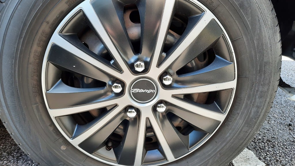
____________________________________ This is not so much a "thing", and more of an essay on using the Z-hop technique I saw on Chuck Hellebuyck's YouTube channel a couple of weeks ago. It's not something that a complete novice should attempt, as it isn't just a case of upload 'n' print!! Chuck used a 0.4mm (2 layer) print height for his logo, but I used a 0.6 (3 layer) for mine, with an appropriate increase on the Z-hop height. ____________________________________ My pal Alan recently bought a small, newly converted, camper based on the Mazda Bongo minivan. In an amusing example of half-hearted badge engineering, some of these vans - Alan's included - were badged with "Ford" logos, front and rear, even though the wheel trims and steering wheel centre boss still carried the standard "Mazda" logo! Alan's original wheel trims had seen better days. So he obtained a cheap set of universal wheel trims to replace them. These new trims complimented the vehicle extremely well but, being universal, had plain centres where importers and end users might wish to add a suitable logo. This tiny missing detail left the trims looking unfinished in a way that was a little jarring on the eye. As we stood looking at it, Al remembered that I had a 3D printer, and asked if it was possible to create something with a personal touch to fill the void. After some discussion about whether a "Mazda" or a "Ford" logo was more appropriate, he suggested that he'd like a simple silver "Bongo" logo, surrounded by a ring in the same colour, all on a black background. Once he said it, there was no question of doing anything else because it was so perfect. So I photographed the "Bongo" logo at the rear of the vehicle, and set about engineering his dream trim piece. My initial thought was to have the letters standing proud of the discs, and to carry out a filament change part way through the print. I've done this in the past, and it's very easy to do. But when I suggested it to Al, he wasn't overly excited about it. But then I remembered that I watched this video: https://www.youtube.com/watch?v=0Sla-vIsvh4 on Chuck Hellebuyck's "Filament Friday" channel, a few weeks ago, and was itching for an opportunity to try the technique. I won't bore you with the detail of how it's done, as I doubt I could explain it half as well as Chuck himself does - To put it bluntly; if you can't see how it works after watching his video, then it's probably not worth reading past this point! Anyroadup, like all good ideas, Chuck's technique turns out to be beautifully simple. But, getting it to work in practice (at least on my machine) was somewhat more problemmatical, thanks to both my BL Touch and my homemade runout detector. Hindsight being what it is, it never even occured to me that Auto Bed Levelling would be an issue - at least until it actually became an issue. So printing the first colour (the logo, in my case) is a straightforward print job if you've paid attention to Chuck. The problem comes up when printing the second colour (the disc, in my case). Because of the BL Touch, my printer no longer uses the original Z-stop switch. Instead, the home position is worked out by the BL Touch's probe. It finds the exact centre of the bed's surface using its diddy little sensing pin. But, if you have a print in the way, the pin can't find the bed, and measures from the top of the first print instead, throwing the print head out of position by the depth of the print! The solution is simple enough: Both parts of the model need to be placed away from the centre point (still properly lined up with one another, obviously), so that the probe can do its thing without the first print getting in the way. So began attempt #2. That's when I hit the second (blindingly obvious with hindsight) problem: When the ABL kicked in for the second colour print, the first print obstructs the the probe again. Again, it's another easy one to fix: This time it's dealt with in the slicing software. I had to temporarily edit the G-code in the slicer's machine settings to disable the G29 command in the start code for the second print. With the ABL inactive, the printer could get on with the second colour - provided, of course, that the bed was good and level when the first print pass was made! At this point I had a third hiccup. I suspect this might be one that doesn't trouble everyone. My slicer (Cura) likes to print a hot end priming line at the left of the print bed before getting on with the actual print. I've never been fond of this line, but I live with it because I get consistently better first layers with it. But, when my print head came in for the second colour, it tried to print another priming line in EXACTLY the same place, not realising that the first print's priming line was in the way. In my case this just gave me a "snotty" nozzle and a few unsightly blobs on the print. But I could easily see it disturbing the printer's movement enough to cause the belt to jump, destroying any alignment between the two separate print runs. To be honest, I could have easily edited this out of the start up code, like I did with the G29 code. But for the sake of simplicity it's easier to just pick off the first print's priming line when you change colours for the second print run! My final niggle came about through my filament runout sensor, and might well be exclusive to my machine: You see, I use a home made sensor assembly - basically a microswitch in a custom mount. But, for some reason, the rapidly oscillating Z-hop motion caused false triggering on this, launching my machine into "filament change" mode with an annoying frequency. Whether this was down to a dry joint in my wiring, a fracture in the switch wire, or just plain ol' contact bounce in the switch is unknown, and I wasn't going to investigate as it works fine the rest of the time. So I simply disabled the runout sensor whilst I was producing the two stage prints and, Bob's yer Uncle, problem solved! I'm indebted to the wonderful Mr Hellebuyck for introducing me to this technique. I find him to be a very relatable guy (although I probably don't watch nearly as many of his videos as I should) and I recommend checking out his channel and giving him a like or three. I also hope that between his video and my over-wordy description, it will encourage those who havent tried this before to give it a shot. Happy printing folks, and remember that you're never alone with a 3D printer!
With this file you will be able to print Bespoke Wheel Centre Caps Using Z-Hop Method with your 3D printer. Click on the button and save the file on your computer to work, edit or customize your design. You can also find more 3D designs for printers on Bespoke Wheel Centre Caps Using Z-Hop Method.