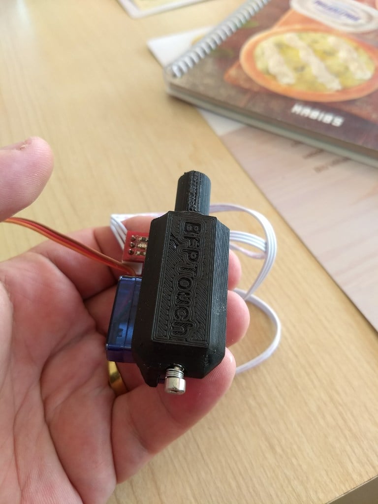
BFPTouch - Poor's man BLtouch. A simple, cheap, neat, precise, compact and reliable any surface Z Proble for bed leveling.
thingiverse
This is a detailed guide on how to set up a BFP Touch probe for 3D printing using the Klipper firmware. The guide covers both the Marlin and Klipper firmware configurations, with specific instructions on how to modify the G-code for homing all axes. Here are the key points from the guide: 1. Connect the BFP Touch servo to a digital output pin (e.g., ar4). 2. Define the probe in the config file using the following code: ``` [servo BFPTouch] pin: ar4 initial_angle: 0 enable: True maximum_servo_angle = 90 minimum_pulse_width = 0.001 maximum_pulse_width = 0.002 [probe] pin: ^ar18 speed: 5.0 z_offset: 1.0 activate_gcode: SET_SERVO SERVO=BFPTouch ENABLE=1 SET_SERVO SERVO=BFPTouch ANGLE=45 G4 P300 deactivate_gcode: SET_SERVO SERVO=BFPTouch ANGLE=5 SET_SERVO SERVO=BFPTouch ENABLE=0 ``` 3. Modify the G-code for homing all axes to include the following commands: ``` G30 ; move Z down until the switch triggers (first pass) G1 Z5 F1800 ; go back a few mm G30 ; move Z down until the switch triggers (second pass) G1 Z10 F1800 S2 ; lift Z relative to current position ``` 4. Test and calibrate the Z probe using the instructions provided in the guide. 5. Send a G29 command to measure and save the mesh, and use G32 at your start gcode to home all axes, measure the tilt, and compensate with the mesh grid. The guide also emphasizes the importance of grounding motors, bed, and frame to prevent static buildup and potential damage to the board.
With this file you will be able to print BFPTouch - Poor's man BLtouch. A simple, cheap, neat, precise, compact and reliable any surface Z Proble for bed leveling. with your 3D printer. Click on the button and save the file on your computer to work, edit or customize your design. You can also find more 3D designs for printers on BFPTouch - Poor's man BLtouch. A simple, cheap, neat, precise, compact and reliable any surface Z Proble for bed leveling..