BI V2.5 V-Slot Conversion
thingiverse
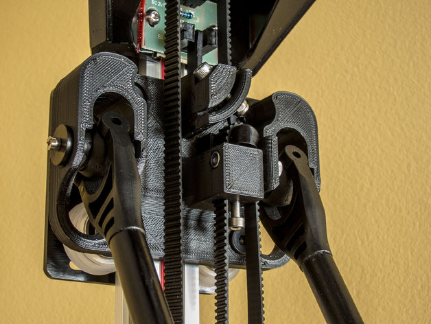
This montage shows what I wish to be an incremental upgrade to magnetic ball joint for the BI V2.5 printer. This is the first part, fully operationnal conversion, using OpenBuilds V-Slot linear rails that keeps the original arms and plastic ball joints. It will also convert the printer from string to belt. The OpenBuilds plates are on the opposite side of the rails, so I can install printed carriages that retain the same ball joints position thus the same arms lenght. WARNING Before buying expensive parts for this retrofit, you should at least print one carriage and try to assemble the inserts and ball joint, see if you can make them fit together (see Instructions). If you're not satisfied with the result, THEN FORGOT ABOUT THIS UPGRADE. Instructions BOM (for upgrading all towers) The rails: 3 x 1000mm V-Slot™ Linear Rail 12 x M5 Tee Nuts 12 x M5x13.5mm Screw Cap (custom cut) The carriages: 3 x 20mm V-Slot™ Gantry Plates 12 x Xtreme Solid V Wheel™ Kit 12 x 40mm Low Profile Screws M5 12 x 6mm - Full Size Wheels Eccentric Spacer 12 x 6mm Aluminum Spacers 24 x Precision Shim - 10x5x1mm 3 x M3 Nyloc 1 x M3x16 screw cap 1 x M3x20 screw cap 1 x M3x25 screw cap The belt conversion: 3 x 16 Teeth 5mm Bore GT2 Pulley 6 x M3 4mm Grub Screw 3 x 212cm GT2 Belt The following item is optionnal, you can use printed parts instead! 3 x Smooth Idler Pulley™ Wheel Kit PRINTING PARTS I've done all printing in ABS with a 0.35mm nozzle, 50% to 100% infill (more than 30 hours print time). Here is the list of parts you need to print, with notes if necessary: 3 x V-Slot Carriage v10.STL This one above definitively needs 100% infill, it must be robust. You'll also need to take extreme care with your perimeter settings. You need to adjust your slicer (I've used Slic3r) to produce a tooth belt profile as clean as possible. You must set the perimeter width so there is only a single pass, or if there is another pass inside the teeth, it is not a crossing one. See the travel moves (little cyan lines) at the top of the belt profile? Best to avoid them. Anyway, go ahead and print it, you'll need to do very fine cleaning at worst. Here is the first warning: DON'T BEND THE BELT CLAMPS WITHOUT A BELT INSERTED. If you do so, the base of the clamp will eventually break. You must overcome the temptation to flex them by hand. 3 x Flag v2 22mm.STL 3 x Belt Tensioner v3.STL The following part is for the OpenBuilds Smooth Idler Pulley™ Wheel Kit. You can skip this part and print the idler pulley support for the existing bearing! 3 x Top Idler Pulley Support v3 for OpenBuilds.STL Print the following parts to use the existing top idler bearing! 3 x Top Idler Pulley Support v3.STL 6 x Half Idler Pulley for 625.STL 3 x Upper Idler Pulley Spacer 4mm.STL (try to print in single wall) 3 x Upper Idler Pulley Spacer 6mm.STL (try to print in single wall) PARTIAL ASSEMBLING Note: Photos not always represent final parts. Before replacing the original rails with the V-Slot ones, you MUST carefully inspect the new printed carriages, and make sure they're usable. Remove one set of the ball joint inserts from the existing carriages, the balls can remains on the arms: the inserts are lightly glued, so you can use an exacto to remove them. Test the inserts on all the carriages, try the ball joint as well, it must slide in freely without restriction. Seeing a small gap on the side of the inserts and the carriage when ball joint is in place is normal. At this step, if you're not satisfied with the ball joint or the inserts alignments, you can try a new print with different settings. Can we continue? Use a nut as lever to insert the eccentric spacers. Install the wheels and back plate on all carriages using the M5 40mm low profile screws. There must be 3 precision shim 1mm washers by wheel assembly; 2 each side of the wheel, and one at the back of the gantry plate (this one is optionally installed for preserving the cosmetic appearance of the plate). Take care to orient the eccentric spacer notch on the outside. Slide the carriage onto a V-Slot rail and make some adjustment with the eccentric spacers. Tighten only enough to remove any slack. Slide out the carriage when test done. You need to carfully inspect its belt profile tooth, located on both anchors, and clean them if necessary. I'm using a small flat screw driver to do the job. As stated in the section above, don't bent the anchors's clamp until a belt is inserted, you risk to break the clamp's base. Use the smallest screw driver that can do the job. The flags must be cleaned as well, their perimeter the same thickness, width and height. Use an exacto to smooth all edges. Insert them carefully, thickness is very important in order not to damage the anchor. You also need to assemble the top idler pulley assembly. You have two options: use the existing bearing and print the idler pulley parts (see Printing Parts) buy the Smooth Idler Pulley™ Wheel Kit (see BOM) Either way, use the original screws and nuts, or use the M5 low profile screws provided with the OpenBuilds kit. The trick to insert the top idler support easily is to have the nut flush to screw's end. THE RAILS The V-Slot rails must be reamed at the end, I've removed about 20mm long to enlarge the slit. This makes room for the cable to exit the V-Slot more gracefully. Use a small file to smooth the cables entry (at the V-Slot edges). You don't want to damage them at their reinsertion. You must now choose how you wish to screw the rails on the corners: New holes Slide in Tee Nuts Drop in Tee Nuts The first option needs drilling and tapping new holes with precision because you can't make further adjustment. For this reason, I've chosen to use regular Tee Nuts (slide in). When all the printed parts are tested, modified and assembled, you can proceed with the final assembly. FINAL ASSEMBLY At this step, you should already have removed the effector with the arms still attached to it, the ball joints remains on the arms. The rails can be replaced one by one, keeping the original cabling in the same rail slit. No need to remove the corners, just unscrew and slide out the rail, remove the original carriage from the top. Keep the printer on its side, it'll be easier when replacing the bottom cable pulleys. Now begins the funny part. Carefully remove the ribbon cables. If some appears to be damaged, it's now a good time to repair them (or after their final install). See pictures to perhaps grab the trick on reinserting the cables. You also see where the file must be used to smoothen any sharp egdes of the rail that can damage the cables. The cables are inserted from one end of the rail to the other. Since you can't remove their connectors, and the connectors doesn't fit inside the rail, you must leave them outside but guide the cables in place. Tricky but doable. When the cables are in place, you can slide a carriage (take care of its orientation) on the V-Slot, then proceed to reinsert the rail. The important thing is you MUST have the same distance between top and bottom corners. My rails was cut with sub-millimiters precision, so I only put them flush to the corners. Replace the bottom cylindrical cable pulleys with the toothed ones: see Belt conversion instruction. Replace the top idler pulley supports with the new ones. If you didn't insert the carriage prior replacing a rail, you'll need to disassemble one side, and loosen the other so it can be inserted sideway. I have put some packing tape over the bottom corner holes, dropping little parts in these holes isn't enjoyable. Don't forget the 3 precision shim 1mm washers. Looks good! Note: Be careful with the following step, the anchor's clamps must be tightened just enough to retain the belt, too much torque will break them. Attach the belt on the carriage's upper anchor, cut flush the exceeding exit belt. Insert the flat side belt through the upper pulley. Twist the belt 180° counterclockwise (looking from the top), pass it to the lower toothed pulley and finally attach it the the carriage's lower anchor (through the small rectangular hole). You can access the head screw of the lower anchor through the arm tip. Just lower the carriage enough to do so. Finally, adjust the tension using the lower anchor tensioner. That's it... Enjoy your new V-Slot driven delta!
With this file you will be able to print BI V2.5 V-Slot Conversion with your 3D printer. Click on the button and save the file on your computer to work, edit or customize your design. You can also find more 3D designs for printers on BI V2.5 V-Slot Conversion.