Bibo Power switch housing
thingiverse
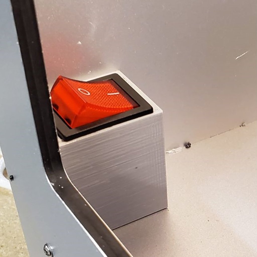
Never reach around your Bibo to turn it off again.... This switch is wired in series with the main power switch on my printer, so either one being off will turn the machine off. Here is what I used. Make your own decisions, I am not responsible for your foolishness. Connectors – you may be able to find three of the largest size connectors in this kit somewhere else, but I like having them around for my projects so I bought the kit. https://www.amazon.com/gp/product/B07GGVBQTN Crimping tool / wire stripper for the connectors (if you need one). https://www.amazon.com/gp/product/B073YG65N2 Switch – This is the one I picked to use, I liked the wide switch. The illumination does not seem to work (in either of the 2 I got) but I don’t really care that much because of the LEDs inside the Bibo. You may have to change the size of the printed part if you use a different one. https://www.amazon.com/gp/product/B07MV5LBX8 Screws – I bought this tray of 3mm screws, it is really handy to have around. But you need 2 M3x12mm screws and nuts for this. https://www.amazon.com/gp/product/B07CYNKLT2 About 4 feet of 14 gauge wire. (Probably bigger gauge than needed, but I am cautious by nature.) Print the housing and the template using the same material. The housing can be printed with the face down without supports (a little extra material droop in the slot for the nuts will help hold them in place.) There is a hole in the floor of the Bibo in the front left corner. I made use of that to route the wires to the switch. There are two notches for wires in the housing. The face with those notches mounts either against the outside left wall or against the floor of the Bibo. The open end goes against the other of those two choices. There are 2 bars that surround the mounting holes, those are deigned to keep a 3mm nut from turning and to space the switch a proper distance from the screws. 1) Unplug the Bibo from the wall. (Your injuries, including electrocution and death caused by not following step 1 are NOT my responsibility!!) 2) The trickiest part for me was getting two holes drilled in the Bibo that match the holes in the plastic case. You may as well start there. I figured out after I was done that it would be easier if you print a second piece that is only the one face of the mounting case that goes against the wall, so I have included that template. Print it slowly so the holes are good. 3) Push that template case piece into the corner. Use a marker to mark the place of the holes. Drill them with a 3.5mm drill bit (9/64” will work) and mount the sleeve using the screw/nut combinations. Note that the housing is designed to hold the nuts from turning. The 3M x 12 mm screws are short enough to not reach the switch itself. 4) Now stand the Bibo on its left side (after sliding the print head all the way left).. Take off the plate on the bottom that hides the electronics you will need a 5.5mm wrench to remove the lock nuts attached to Phillips head screws in the floor of the Bibo. Don’t mix up the spacers as there are 2 short and one long on each screw. 5) The power plug/switch assembly is really a separate power switch and 3-prong adapter. There are 3 wires from the power plug. 2 go to the power supply (the big metal box under the floor), the third (white on my Bibo) is short and goes to the switch. Another lead goes from the switch to the power supply box. Note which tab on the switch this one is attached to (the switch has more than 2 tab connectors, but only 2 are used). 6) Cut a piece of the wire about 30 inches long. Strip both ends and crimp connectors on it. Make sure you put the insulators on the wire before crimping them on. One end will go to the connection on the switch that has the white wire to the power supply. The other end goes through the hole in the corner where you mounted the switch box and plugs into one of the connections on the new switch. (Note – that switch has 2 sets of connections. Use the two connections on the SAME SIDE of the switch.) 7) Now cut another piece of wire to about 18 inches. Put a connector on one end, and connect to the other connection on the switch. 8) Run the other end of that wire through the hole in the floor and down to the power supply box. Remove the white wire that originally went to the back switch, and put this one into that screw. 9) The switch will be hard to push into the case, it is spring loaded to stay against the panel. You may have to set the Bibo back upright to be able to push hard enough to snap it into place. 10) Put the bottom cover back on using the original screws, spacers, and lock nuts. This just has to be snug, you do not have to make it really tight. 11) Double check you are all buttoned up, place the Bibo back on it’s bottom, and plug it back in. Turn both power switches on, and enjoy!
With this file you will be able to print Bibo Power switch housing with your 3D printer. Click on the button and save the file on your computer to work, edit or customize your design. You can also find more 3D designs for printers on Bibo Power switch housing.